Many Mastercam users still work from 2D prints to machine parts and don’t have solid models. In these cases, manual “virtual” measurement tools may still be used to take measurements even in the absence of a solid model. Let’s imagine that you just machined the connecting arm below from a 2D print and don’t have a nominal CAD model to compare against.
In previous blog posts, we showed how to create Regions on the model and then the software will best fit features to the mesh and those features may then be measured for size values, distance values (feature to feature, as shown below) and so on. This provided one method for inspection of a mesh-only. The Features are created, dimensions are taken and compared to values and tolerances shown on the print. Below are the two Bore sizes and the distance between bores using the Regions’ model.
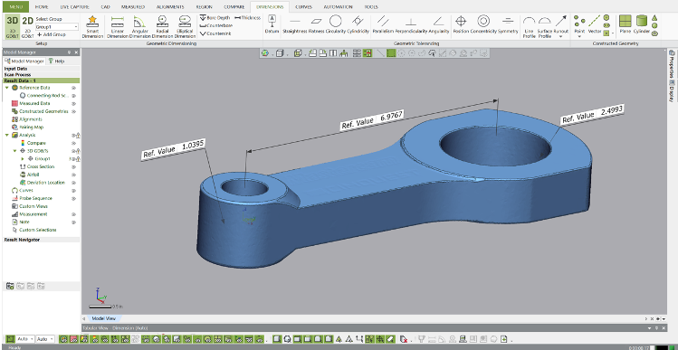
But what if you want to simulate using calipers only to inspect this part? Let’s explore how this tool works. First, we import the scan (mesh or point cloud) into Control X.
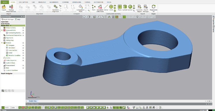
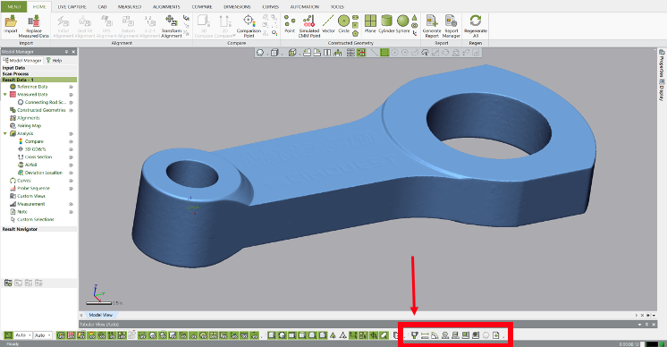
Next, we select the option for Virtual Calipers, located on the bottom right side of the graphics screen. All of the manual measurement and Note creation tools are shown within the red rectangle. But today, we’re focusing just on the usage of Notes and Virtual Calipers.
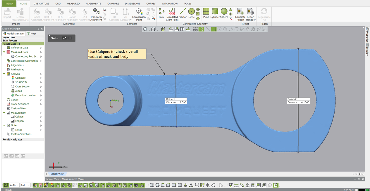
Let’s first measure the overall widths of the connecting arm as shown below using the Outside Calipers setting.
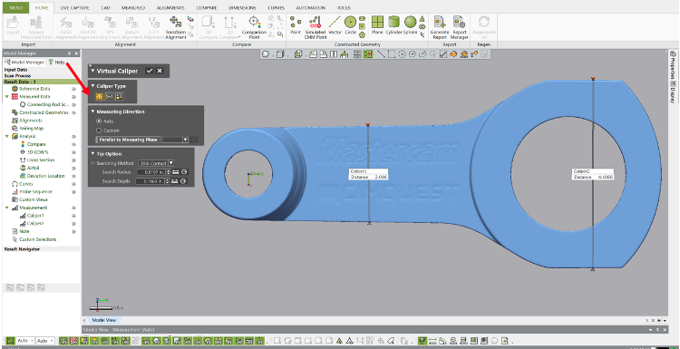
We can also add notes to the Control X screen, to be displayed on the report for the inspector to use for guidance.
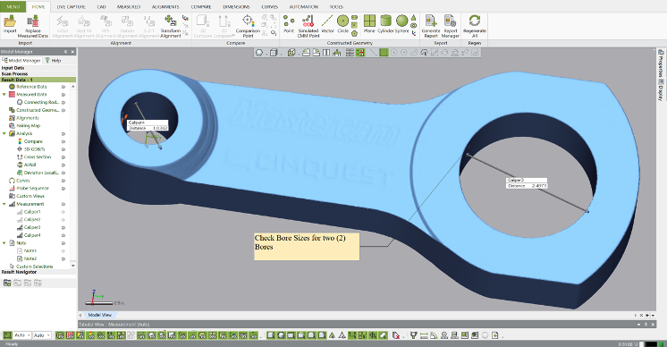
Next, we check the Bore diameters using a similar process with the Inside Calipers and add a similar note.
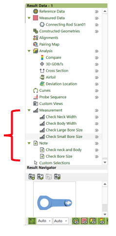
The Notes and Caliper measurements are added to the Model Manager, to later be used for inspection reporting. Custom names may be assigned to any Model Manager item, which is what we did below to identify what each measurement and note is.
Please contact Joel Pollet at Cimquest with any questions.


Leave A Comment