Inspection drawings will often have dimensions created to a theoretical intersection. What this means is that the dimension references one or more points in space that aren’t physically on the model. What do you do in situations like this? Let’s explore this in the example below.
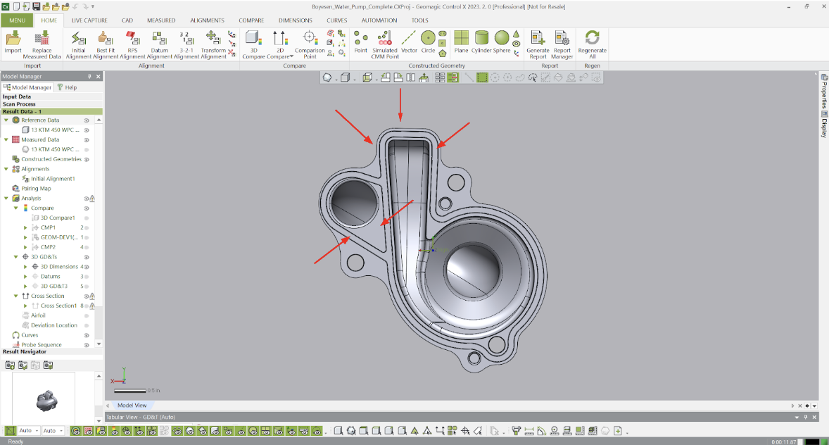
Using the screenshot below, let’s assume that we need to dimension to locations in space where these lines would theoretically intersect if extended.

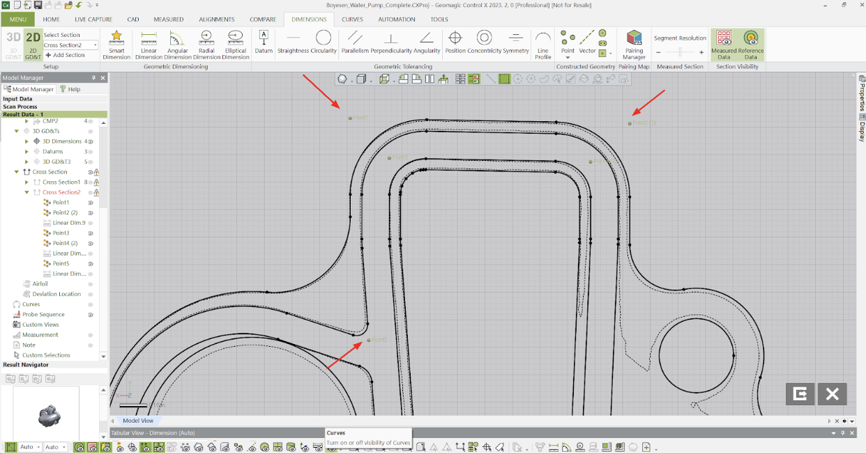
Below you can see the theoretical intersection points of the lines referenced, created using Construction Features in Control X.

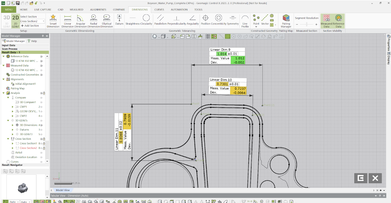
Linear Dimensions 9, 10 and 11 were produced as intersections of two lines on the CAD model to extract their intersection points. As long as those model edges are obtainable from the scan, 2D dimensions from these theoretical intersections can be added anywhere on the model. See below for an illustration.

Please contact Joel Pollet with any questions or to explore more details about Control X.


Leave A Comment