One of our customers was recently faced with the challenge of needing to machine a complex engine port shape without a CAD model, having a circular cross-section on one end, oval on the other and was bent 90 degrees
Due to the bend, the port would also need to be machined, from both ends. Below is a cross section of a similar port with a porting cutter positioned to check the depth we could reach, from one side. It was clear that we would need to address the machining, from both ends.

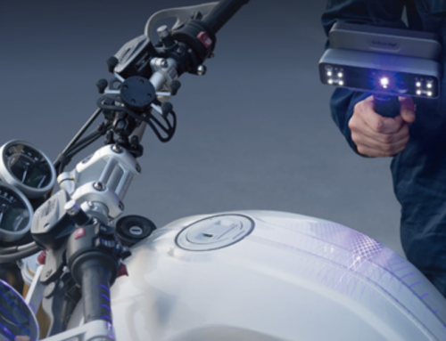
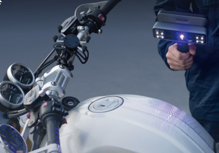
The solution would be to scan the port shape and to then use Design X Go to build a machinable model from the scan data. But that too would prove to be challenging due to the bend in the port. How would we scan this shape when our handheld scanner couldn’t ‘see’ the complete cavity…So we got creative!
We added a partition and separated the port into two (2) sections. We then poured each mold section, let the material harden, pulled them both out and glued them together. This exercise provided us with a physical model of the port shape.

But how do we now go from this physical molded part to a CAD model of the Engine Port? That’s where Design X Go steps in.
We scan the mold using a handheld laser scanner and create an STL model of the final shape. We then import the STL into Design X Go and begin the reverse engineering process.

First, we create a Best Fit Plane through the entire scan. This plane serves as somewhat of a bisecting plane.

We then sketch an approximate port centerline on the plane.

We then create planes along the centerline curve, remaining normal to our centerline.

Next we ‘Mesh Sketch’ on each of these normal planes, producing the cross-sectional curves required to form the final Lofted surface.

Finally, we build a Lofted surface in Design X Go incorporating each of the cross-sections created from the previous step.

Design X Go then exports the surface as a Step file. The file is now ready to be imported into your CAM system to create multi-axis CNC toolpaths.
Whether the reverse engineering requirements are for simple, prismatic shapes or extremely complex, multi-axis parts, Design X Go serves as an excellent reverse engineering tool to go from mesh or point cloud data into completely usable CAD models.

Please contact Joel Pollet (joel.pollet@cimquest-inc.com ) with any questions or to obtain additional information regarding Design X Go.

Leave A Comment