Batch Processing in Control X Professional
This month, we continue to explore the Control X Professional Automation tools. Last month, we took a look at the Airfoil Analysis tool. This month, we focus on Batch Processing.
Batch processing enables the user to create an inspection plan using a nominal CAD model and can then automatically assign the same inspection criteria to any number of scans, located on the user’s network.
First, let’s explore each of the Model Manager tools used to inspect this water pump housing.
Nominal CAD model

First Scan to be Inspected

The Datums used to align this and future scans to the same nominal CAD model

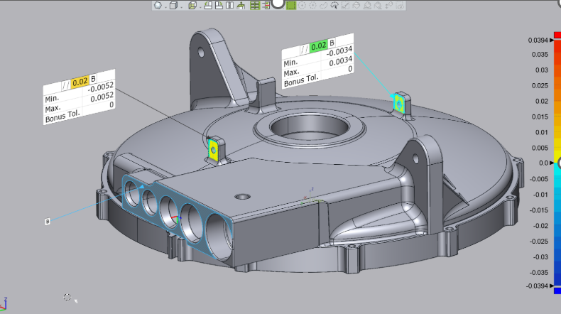
A 3D Color Map, showing global tolerances that fall within an acceptable range

Random deviations at point locations, showing critical areas of the housing

Critical Hole Locations

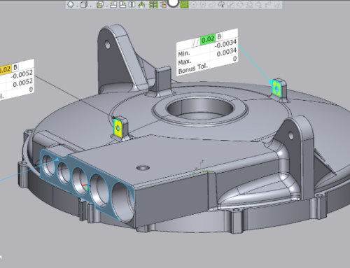
GD&T Specified on the Print

2D Fillet sizes

")
Then once the inspection of the initial scan is completed, checked and tested, the identical inspection plan is then applied to any number of additional scans of manufactured parts using the Batch Processing tool. This tool identifies where the scans are located, the Output options, the Output Destination and the file naming conventions to use. Then, once selecting OK, the batch process begins, inspecting every scan selected, utilizing the inspection criteria defined.


