Performing a Datum Alignment using Control X
Before the scan of a manufactured part can be inspected using Control X, it must first be aligned to its nominal CAD model. The nominal CAD model represents the ‘perfect’ shape. Once aligned, all of the Control X inspection functions, including Color maps, Whisker plots, 2D and 3D dimensions, Geometry Deviation, 2D Twist Analysis and more can all take place.
Consider the water pump cover shown below, prior to alignment.

The datums to be used for alignment can all be found on the mating side of the cover. The Primary Datum, Datum A, is the mating face on the underside of the cover. Datum B is the large cylinder and datum C is the small hole that will clock the alignment.
The datum Alignment tool makes simple work of aligning the scan to the nominal CAD model by matching up the analytic features that were selected as datums on the nominal CAD model. The software can distinguish the matching features on the scan and perform the alignment with three simple clicks on each datum surface.

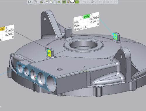
After alignment, the software returns any alignment error for the Primary, Secondary and Tertiary datums.

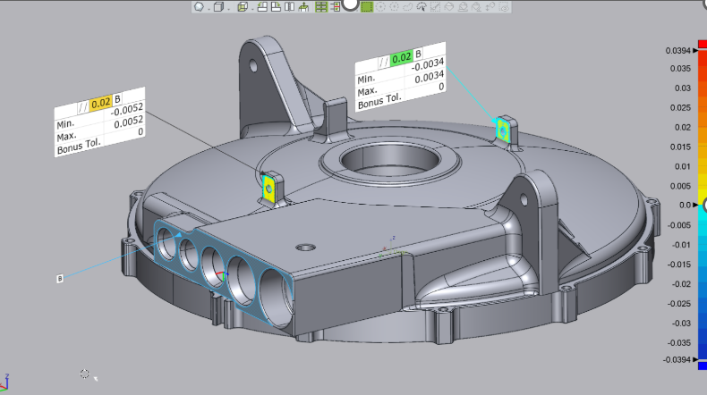
Once aligned, any of the inspection functions offered by Control X may be executed and the program can determine the accuracy of the manufactured part. Below we show a 3D Color Map, a Linear Dimension and a GD&T Callout.


Well, this concludes this month’s Metrology Minute. Please contact Joel Pollet with any questions. Joel.pollet@cimquest-inc.com.


Leave A Comment