Repositioning a Crankshaft in Control X
In this blog post, we’ll explore how to reposition the nominal CAD model in Oqton’s Control X so that inspection information is reported based on the main assembly’s coordinate system rather than the local subassembly. We’ll use a crankshaft as our example.
Introduction to Crankshafts
Crankshafts are essential components in piston engines, converting reciprocating motion into rotational motion. Before diving into the repositioning process, it’s advisable to reposition the model before aligning the scan and adding any inspection criteria.
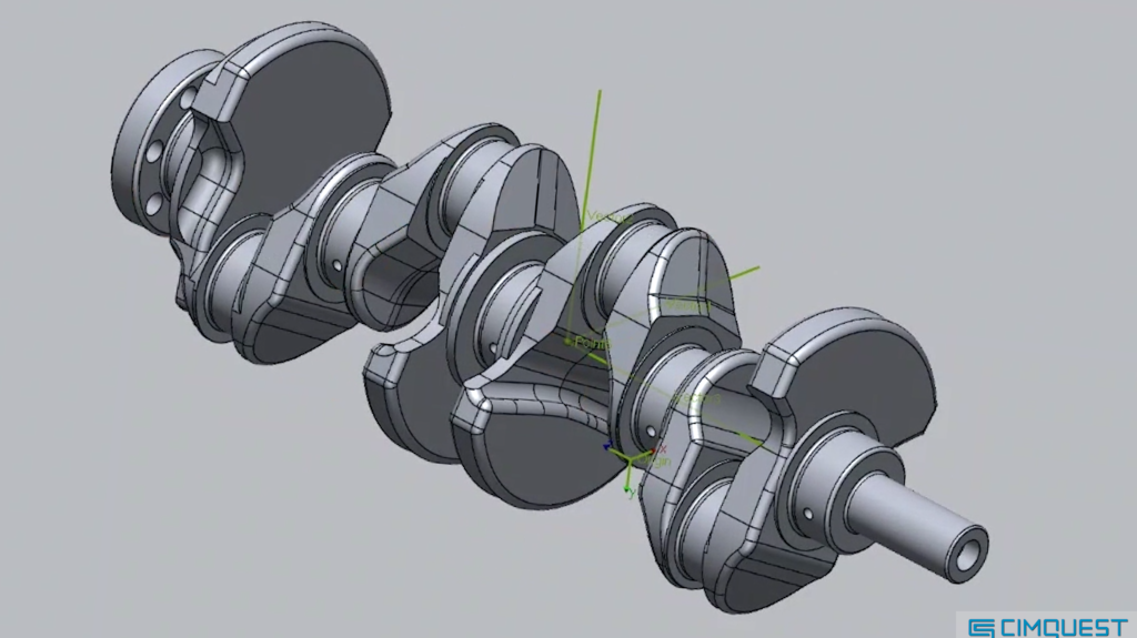
Model of a crankshaft.
Why Reposition?
CAD designers often create subassemblies like this crankshaft at a convenient location. However, when it’s time to report inspection information, it’s usually preferred to have the data based on the coordinate system of the entire vehicle or assembly, not just the local subassembly.
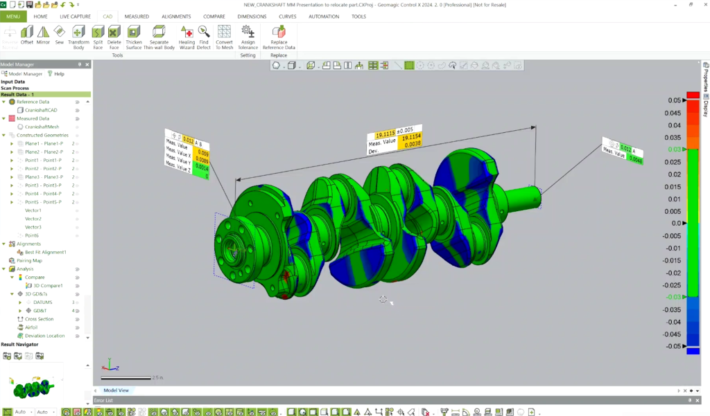
Subassembly of a crankshaft at a convenient location.
The Repositioning Process
Control X offers several options for relocating the reference model. Today, we’ll focus on the Transform Body tool using an Interactive alignment. This method allows us to specify the new location and orientation using two vectors and a new origin point.
- Original and New Positions:
- On the left pane, the part is shown in its original position and orientation.
- The right pane displays how the part will be repositioned.
- Specifying Axes:
- We specify the X and Z axes, which can be flipped or used as is. These axes determine the part’s new orientation.
- Selecting the New Origin Point:
- The part is physically moved to its new location within the final vehicle assembly. It’s generally preferred to reorient the part first before moving its origin, but the order can be adjusted based on user preference.
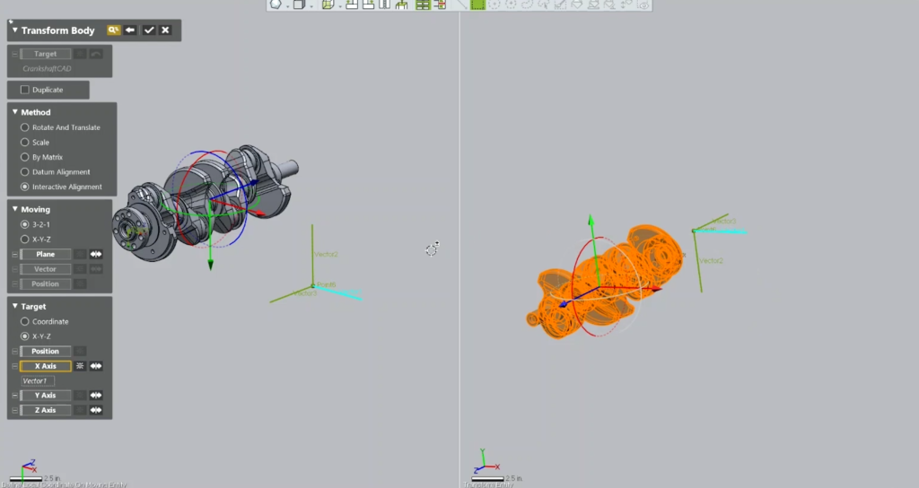
Left pane: Part shown in its original position and orientation.
Right pane: Preview of how the part will be repositioned.
Final Steps
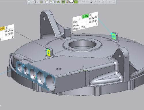
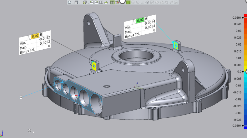
After accepting the command, you can begin creating your inspection items.
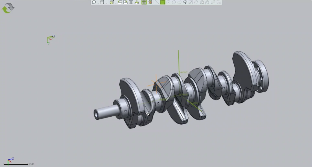
The part in its new location in the final vehicle assembly.
Control X is a versatile tool that can be tailored to fit your specific needs. That’s it for this guide on repositioning a crankshaft in Control X. We hope you found it helpful and look forward to sharing more insights in future posts.


Leave A Comment