The Geometry Deviation tool in Control X may be used to compare all the parameters of an analytic feature in a scan to the nominal CAD model. This tool provides the ability to thoroughly analyze cylinders whereby the values for both the nominal CAD model and the paired (scan) data are compared. In many cases, the most common feature to check is a cylinder. In this Metrology Minute we are going to show you how to do a thorough analysis of two bores using our sample part.
In the example below, the Diameter represents the diameter of the nominal CAD model, and the Paired Diameter represents the diameter of the scan.
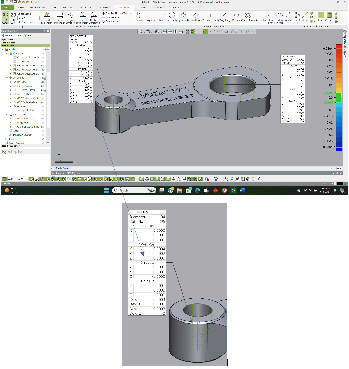
The Position and Paired Position reference the differences in the cylinder center point location and the Direction and Paired Direction provide a comparative analysis for the centerline vector of the CAD cylinder as compared to the scanned (or machined) cylinder.
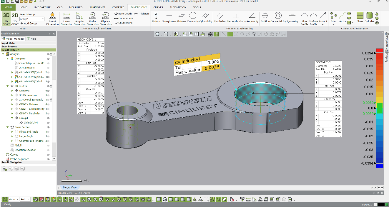
Using this tool in conjunction with the Cylindricity GD&T tool can tell us anything we may need to know about the geometric integrity of the cylinders. So below, we can tell that the large bore is within Cylindricity tolerance but approaching values where it will be OOT.
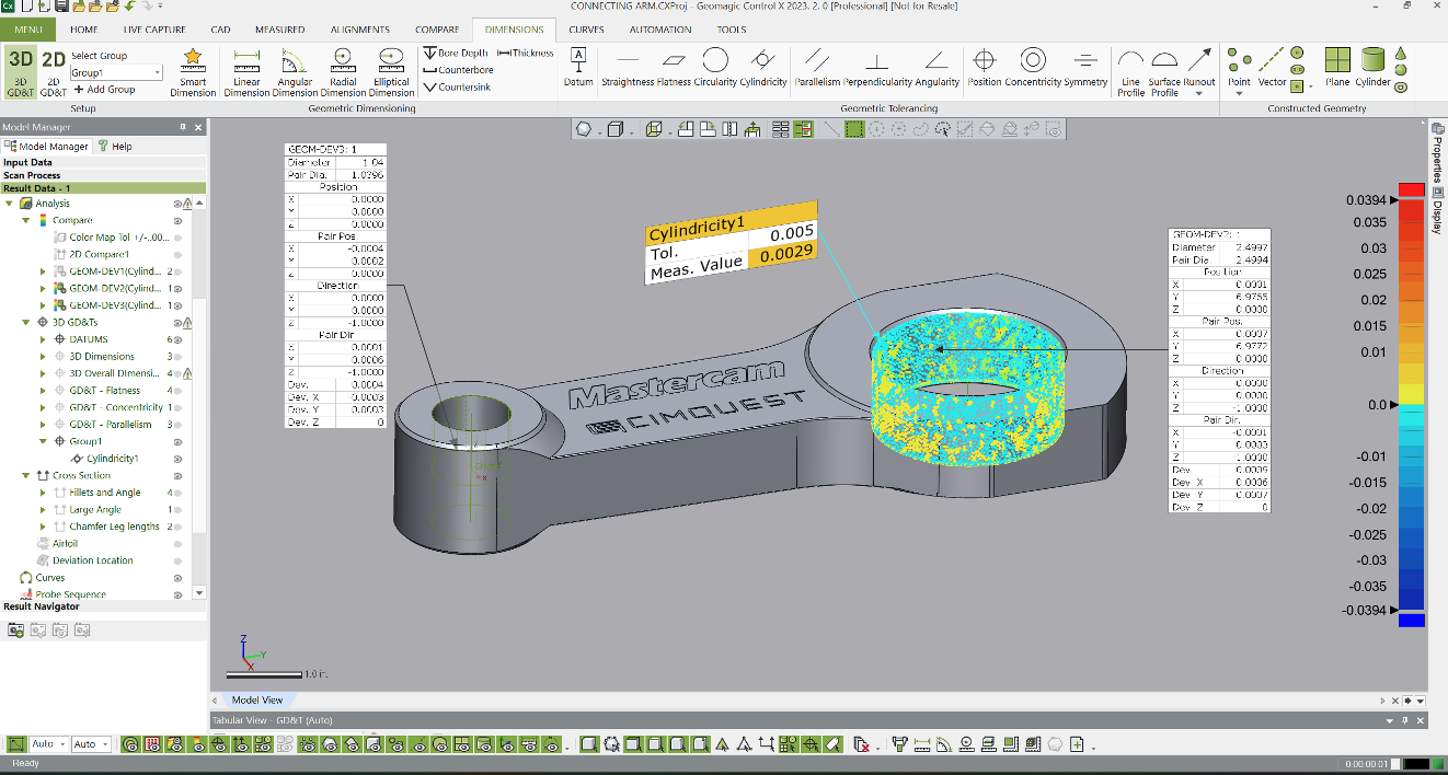
We can then turn on the Fitting Deviation color map whereby Control X will not only tell us by how much the cylinder is out of Cylindricity but exactly where the deviations are.
Based upon the image below and the results from our Geometry Deviation analysis, cutter chatter during the machining process likely was the main contributor to the Cylindricity value being nearly OOT.
Adjusting feedrates and/or spindle speeds may improve the Cylindricity outcome for this bore. These tools in Control X would enable a CNC Programmer to dial in such parameters.
Please contact Joel Pollet with any questions.


Leave A Comment