Meet the ETEC Pro XL 3D Printer
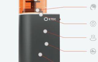
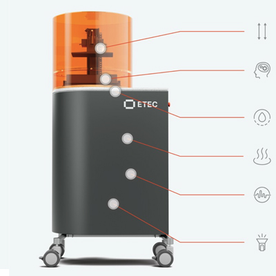
The ETEC Pro XL is an Industrial Polymer 3D Printer that Drives New Affordability in Premium DLP Technology at Half the Price of its Predecessor Designed for a 24/7 production environment, the ETEC Pro XL 3D printer can run lights out, with little to no user intervention required. Easily print parts at volume with the quality, surface finish and tolerances needed for end-use applications. Built on a foundation of quality The next generation of the first DLP 3D printer to hit the market 20+ years ago, this trusted platform features a 4K UHD projector for optimum build size and pixel resolution. UV optics tuned to 385nm wavelength deliver 5mW/cm2 power density that translates into faster layer exposure times and ensures the maximum amount of energy is transferred from the LED light source for exceptionally precise curing. The Pro XL delivers high accuracy and high throughput, consistently, to keep your large-scale production on schedule. Automated optimization with Hyperprint™ Hyperprint technology uses print force data to optimize build layers. An efficient combination of heat and closed-loop feedback, driven by intelligent load sensors detecting forces exerted on the part, fully customizes how each print layer is processed for repeatability, quality assurance, and speed. Key Features Build [...]
What are Some Advantages of Metal Additive Manufacturing?
There are several industrial possibilities within additive technology that can change the future and bring the industrial world into a new era. In this blog post, you will find some of the most important features of metal 3D printing which constitutes the strength of metal additive manufacturing. Simpler, Faster, Cheaper Prototyping Every time we talk about additive processes and additive technology, we mention how excellent it is in prototyping processes and R&D departments. It speeds up decision-making, increases the creativity of creators, reduces costs, and shortens the time a new product enters the market. However, metal 3D printing technology takes it to a much higher level and makes the process even easier. Like no other commonly known technology, it gives us: Possibility of using the final material and functional prototyping: Many times we encounter companies interest in incremental processes in terms of the initial design of new elements. Now, metal 3D printing makes it possible to produce functional elements that can be tested and checked in final operation conditions. This is a great change in work methodology and risk minimization – which is a key element of a safe R&D process. Possibility to improve the design at any time: You need to add [...]

Cimquest Looking Ahead to the 2024 New Year
The Cimquest team is ready and excited to continue being your manufacturing partner in 2024. We look forward to continually bringing you high-value content that helps you make the right choices for your business. Here are some of the upcoming items that you can look forward to in the upcoming year. These are not all that will be new, so stay tuned throughout the year for more informational webinars, events, white papers, 2MTs, and other content! CimCast: Cimquest's newest informational video podcast where we take a deep dive into market trends and new products while making comparisons, providing you with the full picture. We'll even have some of our team's projects featured from time to time. New Mastercam Training Class: Cimquest is happy to offer a new Mastercam Router class, covering the key points of programming your CNC Router. This is a foundational class on 2D router toolpaths that includes the topics of nesting, block drilling, patterns, tabbing, and aggregate heads. Kimya Partnership: We're happy to announce that we will continue our partnership with Kimya in 2024. Kimya offers innovative solutions that use made-to-measure 3D materials adapted to the needs of the industry. Website Updates: Cimquest's team takes their website and the [...]
Benefits of Using 3D Scanning in the Automotive Industry
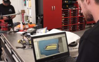
We recently posted a blog article about reproducing legacy auto parts with 3D scanning; this post is a follow-up to it. Today we are going to list just some of the benefits of using 3D scanning in the Automotive industry. This list is not exhaustive, but hopefully one of the applications or challenges listed here resonates with you. Whether you work for an OEM or a small custom shop, automotive designers, manufacturing engineers, R&D teams, quality inspectors and many other stakeholders can expect to benefit in several ways by bringing 3D scanning into their operations: Lower costs. As we have seen in many of these examples, using 3D scanning can streamline multiple steps in the design cycle, leading to faster design, prototyping, testing and manufacturing of vehicle parts. This means faster time to market and lower production costs. Faster design cycle. Before 3D scanning, modifying an existing automotive part often required extremely slow, low-resolution measurement using manual tools like calipers, gages, rulers or CMMs. Then a model or drawing would need to be created by hand to inform the modelmaker or prototyper before the part could be reproduced. The more complex the part, the more measurements were needed, and the more chances for missing [...]
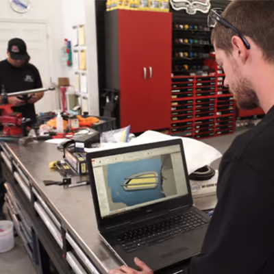
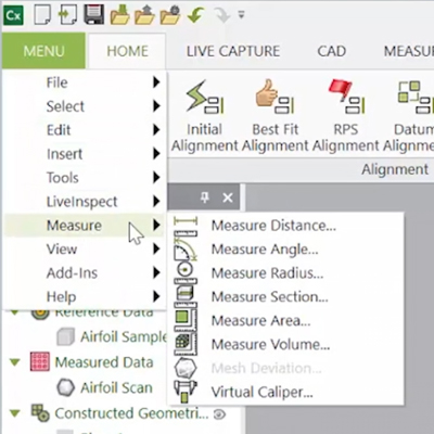
The Various Control X Measure Functions
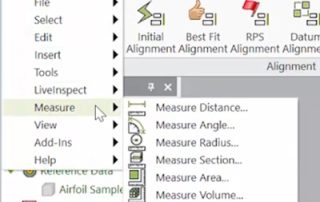
There are many different measurement functions that can be used in Control X Professional. This post will explain what they are and how to use them. We will use the airfoil example above to illustrate the various Control X measure functions available. In the menu below you will find a list of the measurement tools that are available within Control X. These all apply to just the MEAsured data. The Measure Distance function allows you to simply pick two points on the mesh or point cloud and request the distance between them. Measure Angle enables you to select three points off of the mesh or point cloud and Control X will return the angle between them. The Measure Radius function also allows you to select three points, but returns the radius fit between those points. Measure Area is a 3D measuring tool that enables you to measure the surface area in “units squared.” The Measure Volume tool enables you to measure the volume of either a fully enclosed region or a region bound by a surface and a plane. The volume is returned in “cubic units.” If you are a Control X user and haven't tried out these measure functions yet, give them [...]

Vendor Spotlight: Xact Metal
Vendor Spotlight: Xact Metal Cimquest visits their vendor, Xact Metal, to discover how their 3D printers are made, meet the team, and learn about the company's inner workings.