Designing and Producing Hand Orthosis With Artus3D and the Fuse Ecosystem
Designing and Producing Hand Orthosis With Artus3D and the Fuse Ecosystem Artus3D, based in Ridderkerk, the Netherlands, offers orthotists an all-in-one solution for creating hand orthotics. With seven years of experience, they initially outsourced their 3D printing but faced challenges with reliability and shipping times. This changed when they discovered the Fuse 1+ 30W selective laser sintering (SLS) 3D printer and TPU 90A Powder, allowing them to bring production in-house. This move gave them more control over their production, saving both time and resources. Intuitive Digital Workflows The Fuse 1+ 30W printer, designed for maximum output and minimal waste, enabled Artus3D to produce orthotics rapidly and efficiently. Their software simplifies the design process, allowing orthotists to create custom hand orthoses with basic 3D printing knowledge. Users can adjust designs, select materials, and print orthotics in-house or order them directly from Artus3D. Once designed, the orthotic can be ordered from Artus3D or exported as an STL for printing. The software will automatically generate a proposed hand orthosis, at which point users can adjust designs. Then, Broxterman says, “You select the material you want to print in. There are some settings preset. The software gives a preview of how it thinks the orthoses should look. From there, you [...]
Reaching Solutions by Scanning for 3D Printed Prosthetics
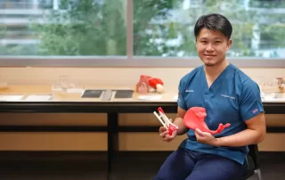
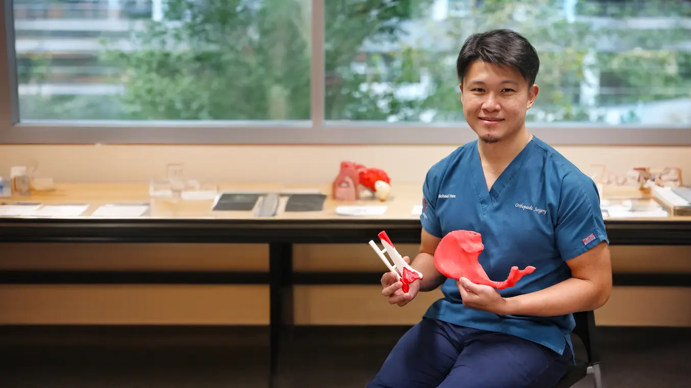
Healthcare providers use 3D printing to enhance training, optimize pre-surgical prep, and create personalized tools. TTSH uses versatile resins for realistic prostheses. Transforming Patient Care at Tan Tock Seng Hospital’s Medical 3D Printing Centre Emergency surgeries need swift responses, making third-party vendors impractical. TTSH established an in-house 3D printing lab for timely, accurate solutions. The Centre, operational since 2020 and launched in 2022, 3D prints organ models for clearer medical explanations and surgical tools for practice. It uses Formlabs’ Form 3B+ and Form 3BL printers with biocompatible materials. The Challenge In 2022, 73-year-old J. F. Lian, battling skin cancer, had most of his nose removed. TTSH offered him a 3D printed nose, identical to the original, as a pilot project. Skin cancer survivor Mr. J. F. Lian with his 3D printed face model and prosthetic nose. The Solution A colleague suggested 3D printing a prosthetic nose for Lian. Dr. Yam, always pushing boundaries, agreed. In November 2022, TTSH custom-designed and printed a resin nose based on Lian’s face scans. The process involved creating a 3D print file from CT scans, printing, cleaning, curing, and finishing the model. Dr. Yam aims to make 3D printing more accessible to patients. [...]
Biggest 3D printing farm in Finland Aalto University’s Innovative Workshop
Biggest 3D printing farm in Finland Aalto University’s Innovative Workshop Aalto University in Espoo, Finland, hosts the country’s largest 3D printing workshop, equipped with 35 UltiMaker 3D printers. This workshop, led by Hector Velasquez, integrates traditional and digital manufacturing techniques, allowing students to explore and innovate in fields like fashion, architecture, and product design. The collaboration with UltiMaker has significantly enhanced students’ creativity and innovation, providing a dynamic learning environment with a wide range of materials, including PLA and TPU. Photo: Wenla Nwajei The workshop emphasizes practical learning, where students independently design and produce 3D printed pieces, taking responsibility for their projects from start to finish. This hands-on approach fosters creativity and innovation, enabling students to tackle complex 3D printing projects. The interdisciplinary nature of the workshop encourages collaboration among students from various fields, promoting a lively exchange of ideas and the development of new innovations. Aalto University’s investment in 3D printing research and training has positioned it as a significant player in the global 3D printing field. The workshop’s impact on students’ creative learning and innovation is profound, demonstrating the limitless possibilities when combining knowledge, skills, and technology. This commitment to education and innovation ensures that Aalto University remains at the forefront of 3D printing [...]
Turning an Organic Toy Design into a Manufacturing-Ready Model
Today's toy aisles showcase a wide range of shapes, from realistic animal figures to imaginative cartoon characters. Most of these toys are made of plastic, with their creation involving two primary steps: design and manufacturing. The challenge of designing toys is compounded during the manufacturing stage. Plastic injection molding is the most common method used, where detailed 3D designs are turned into molds for mass production. Effective software plays a crucial role in this process, simplifying the workflow and reducing the need for multiple steps. In this guide, we explain how leading toy companies efficiently manufacture detailed toys, creating figurines and objects from organic designs that entertain both kids and adults. Streamlining Toy Manufacturing with Digital Workflows 1. Designing toys in 3D The design phase kicks off any toy-making project, whether it’s a sketch, a 3D scan, a CAD model, or an adaptation of an existing item. Key considerations include the manufacturing process and the final size of the toy. For example, if the toy replicates a real-life vehicle, start by laser scanning the actual vehicle. This captures its shape, which you can then import into 3D modeling software to refine and adjust the design. For toys modeled after real objects, start [...]
Mastercam 2025 Rollout Replay
Mastercam 2025 Rollout Replay Watch the replay of our Mastercam 2025 Rollout Event on August 6, 2024. Join Cimquest as we discuss the latest and greatest features of the new Mastercam 2025!
De-risking Industrial 3D Printing with a Simple, Repeatable Simulation Workflow
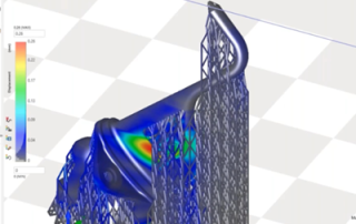
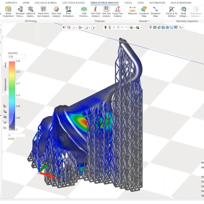
Radical weight reduction, enhanced performance, and short lead times. These are just a few advantages that drive aerospace companies to adopt 3D printing. But one major challenge is deterring them from fully committing to the technology – the hefty price of mistakes. The materials alone are so expensive that printing a single part sometimes costs tens of thousands of dollars. Additionally, aerospace parts need to comply with exacting standards where the tolerance for errors is low. Mistakes that would be considered insignificant in other industries are inadmissible in aerospace. The high cost of printing underscores the need to reduce the likelihood of mistakes and de-risk additive manufacturing. Simulation is part of the solution. With the simulation and compensation tools in Oqton’s 3DXpert software and a simple workflow, you can print parts right in record time and eliminate material waste. Capturing additive manufacturing expertise In the infancy of additive manufacturing, the risk of build failure, deformation or overheating was simply something manufacturers needed to accept. With time, experts gained sufficient process knowledge to avoid common pitfalls. Today their experience is captured in simulation tools, enabling users to identify and prevent problems before they occur. However, not all simulation tools are made equal. If you [...]