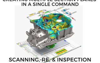
Control X – Creating Multiple Section Planes in a Single Command
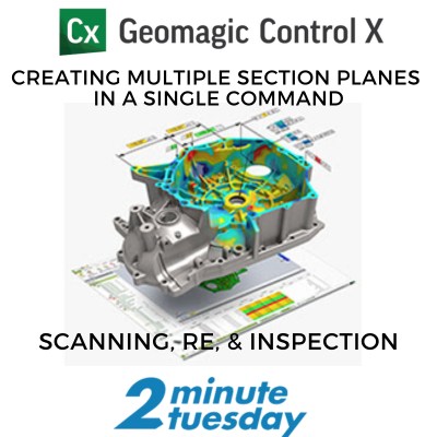
In this week's 2 Minute Tuesday, we are going to demonstrate the creation of multiple section planes in a single "2D Section" command in Oqton's Geomagic Control X.
In this week's 2 Minute Tuesday, we are going to demonstrate the creation of multiple section planes in a single "2D Section" command in Oqton's Geomagic Control X.
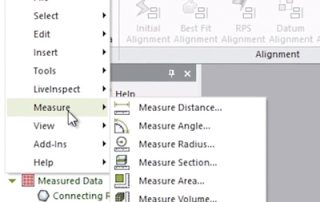
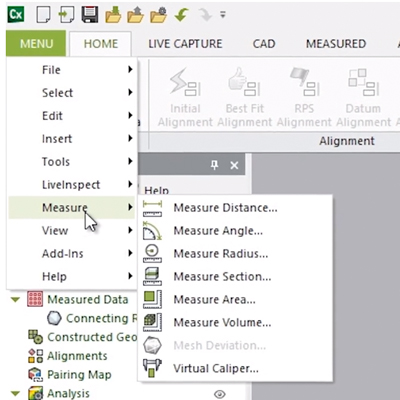
This blog post will delve into the Measure Menu of Geomagic’s Control X software. While most users of Control X are interested in producing color maps, whisker plots, dimension checks, and GD&T analyses of the scan as compared to the nominal CAD model, it is important to note that there are several “mesh-only” functions for measuring a scan model that do not require a nominal CAD model. Geomagic Control X Measure Menu Options The Measure [...]
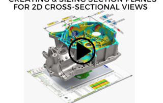
In this week's 2 Minute Tuesday, we will examine how to resize section planes so that just the necessary geometry is displayed in Geomagic Control X. This becomes extremely useful for very complex models where you want to draw the reviewer’s attention to a specific location on the model.
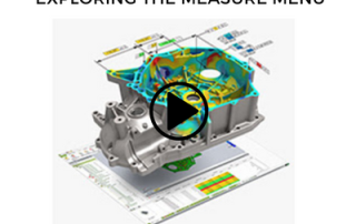
In this week's 2 Minute Tuesday, we delve into the Measure Menu of Geomagic’s Control X software, examining the features it offers. While most users of Control X are interested in producing color maps, whisker plots, dimension checks, and GD&T analyses of the scan as compared to the nominal CAD model, it is important to note that there are several “mesh-only” functions for measuring a scan model that do not require a nominal CAD model. [...]
In this week's 2 Minute Tuesday, we take a look at how to manage a Geomagic Control X project when the user has 10, 100, or even 1000 scans to inspect against the same nominal CAD model.
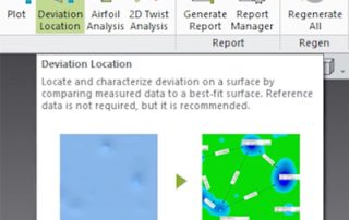
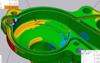
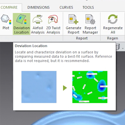
Today’s post will cover the Deviation Location tool in Geomagic Control X. This tool creates a Best Fit Surface over an area of interest and enables you to analyze isolated areas on a part for wear, dents, bumps, corrosion, etc. While Reference Data is not required for this function, it is recommended. This tool takes measurements in an isolated location of the part and requires the existence of either a coordinate system or two vectors [...]
In this week's 2 Minute Tuesday, we will take a look at how analyzing airfoil shapes is easier than ever using the Geomagic Control X Airfoil Analysis technology.
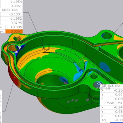
This blog post will show you the Comparison Point Analysis tool which enables a Control X user to click arbitrary or specific point locations on the Reference CAD model and compare them to the corresponding point mapped to the Measured mesh model. This is a very useful comparison tool for identifying the accuracy of random point locations on the manufactured model. The typical method of mapping points is by using the Along Normal vector option, [...]