Very often, when a part is designed in CAD, in terms of its orientation and origin, it isn’t necessarily where it needs to be oriented in the final assembly. Therefore, inspection values may not reveal the true picture as to what is needed regarding inspection data.
Let’s consider this crankshaft below. The CAD designer created this sub-assembly with the part’s origin as shown.
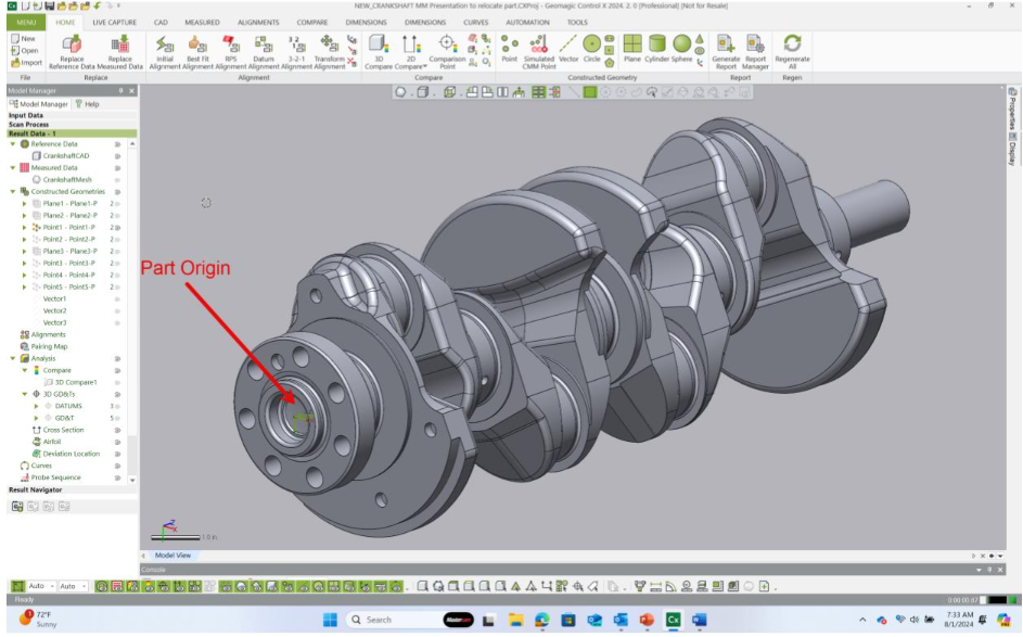
Then, any distance or location dimensions shown in the inspection will be relative to this sub-assembly origin.
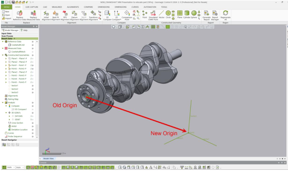
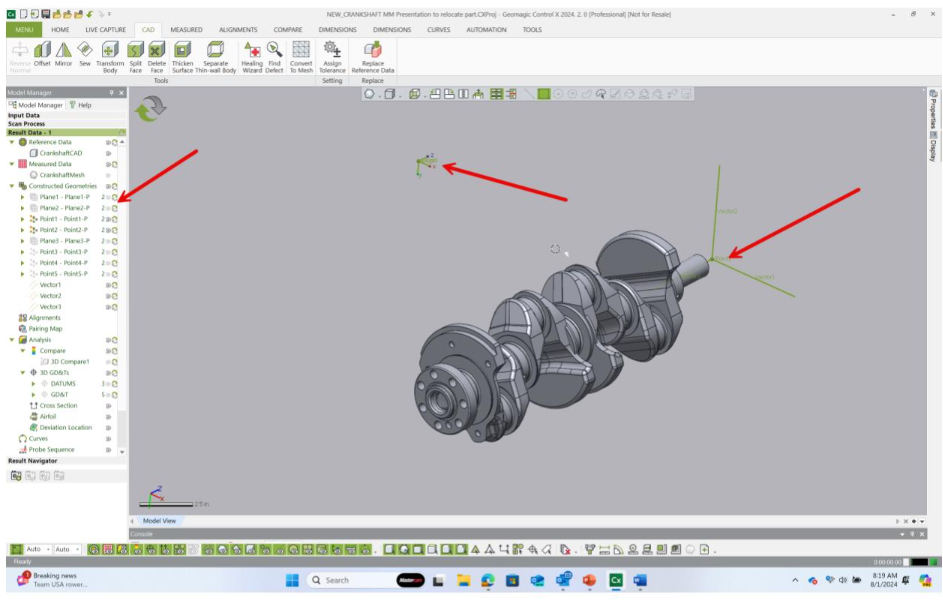
Let’s now go through the steps of relocating the sub-assembly to the correct location in the vehicle so dimensions are evaluated properly. The three green lines below represent the location point and orientation of where the sub-assembly of the crankshaft needs to move.
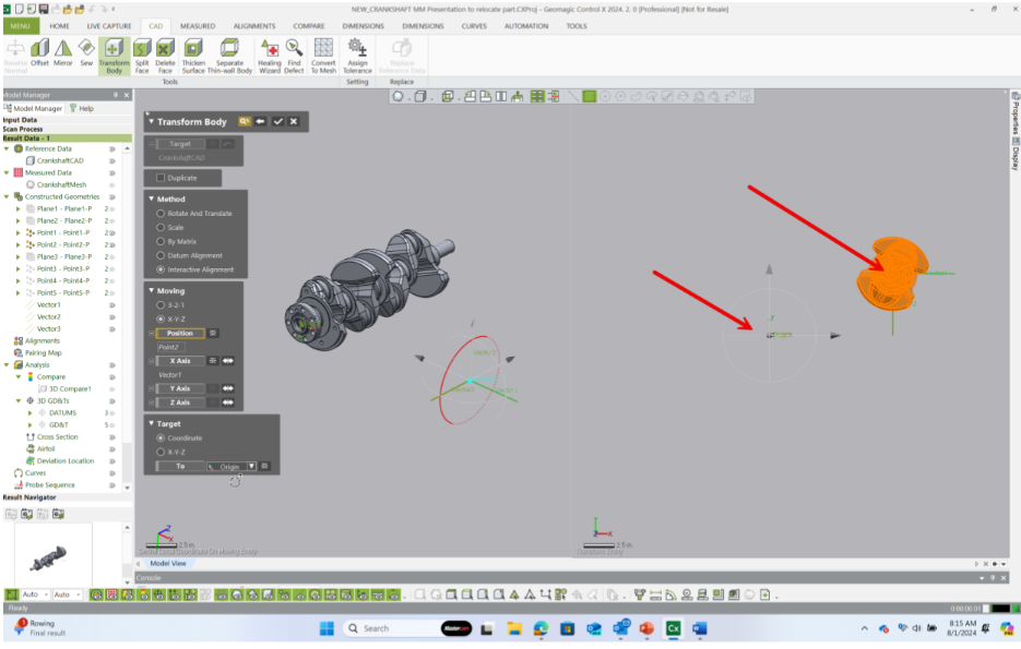
From the CAD tab, select Transform Body.
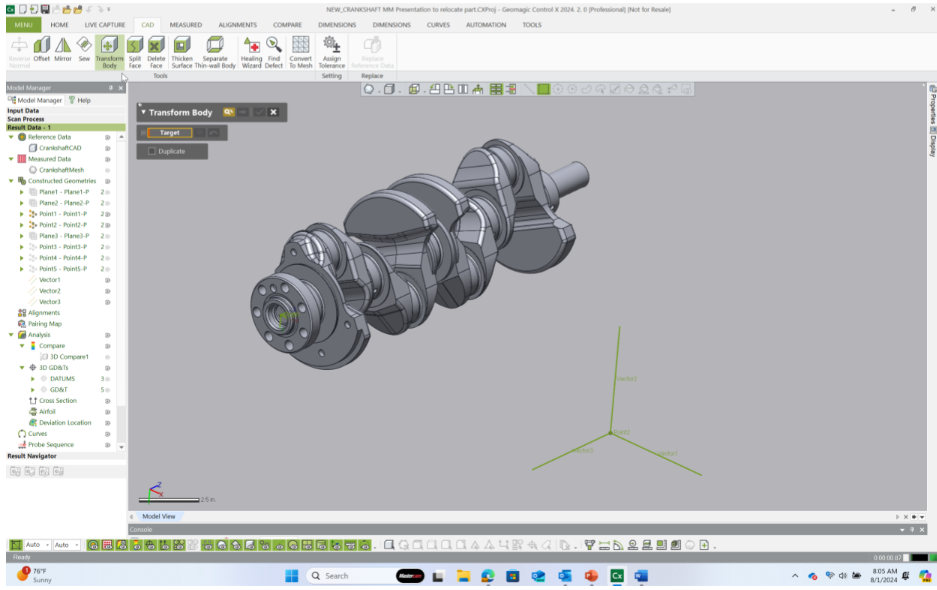
Select the CAD model and select the arrow in the menu to continue forward through the command.
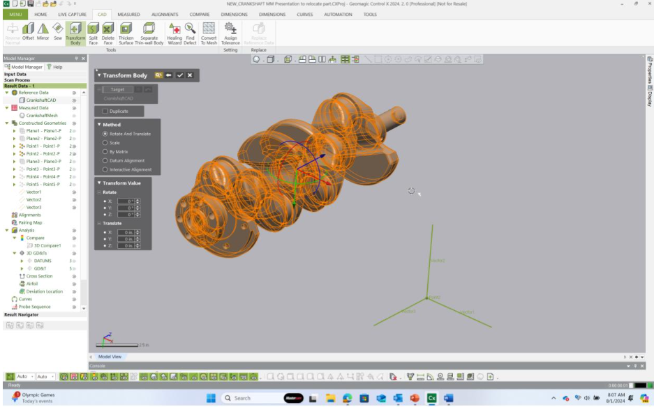
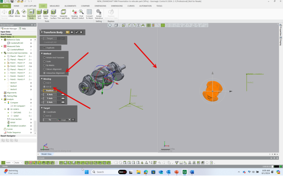
We used the Interactive Alignment method to reposition the crankshaft to the proper location in the vehicle.
After selecting Interactive Alignment, select the XYZ option. The screen will then divide into two sections.
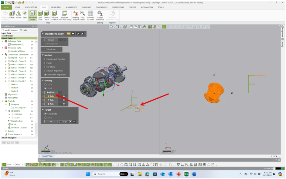
Select the X-Axis option and then select the horizontal vector as shown below.
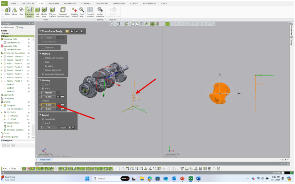
Do the same by selecting the Y-Axis vector and the vertical vector shown below.
Lastly, select the Position button and select the origin point of the new coordinate system. This is the point where the three lines intersect.
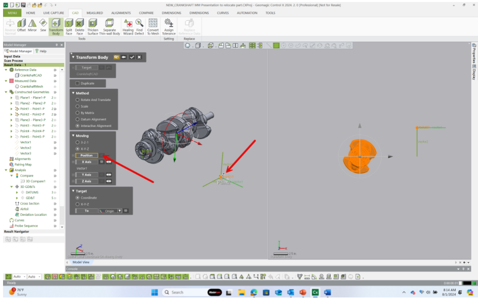
The part now shifts to the new location.
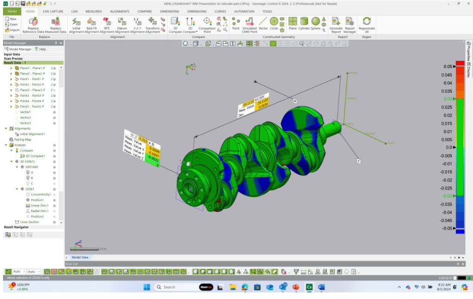
By completing the command, the part is now physically shifted to the new coordinate system and all of the analysis items in the Model Manager need to be regenerated in order to update to the new location.
Regenerating the model now rebuilds all dimensional Model Manager entities from the correct location and orientation relative to the true location in the vehicle.
Please contact Cimquest with any questions.


Leave A Comment