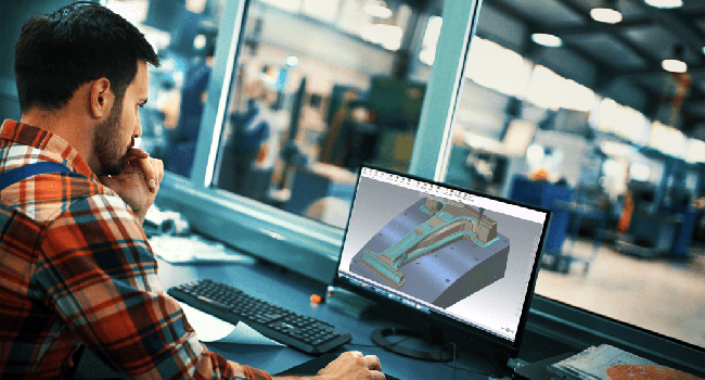
When someone mentions CAD programming, odds are they will also bring up CAM programming in the same conversation. Some people even erroneously use the two terms interchangeably. If the two software systems are so intertwined, where is the line between the two drawn? The answer lies in the stage of manufacturing in which each is used.
CAD stands for Computer-Aided Design (in some circles, it can refer synonymously to Computer-Aided Drafting), which refers to the design or modification of a digital model. CAM, on the other hand, is Computer-Aided Manufacturing and controls the machine used to produce a part. CAM draws the CAD model into the real world.
CAD 101
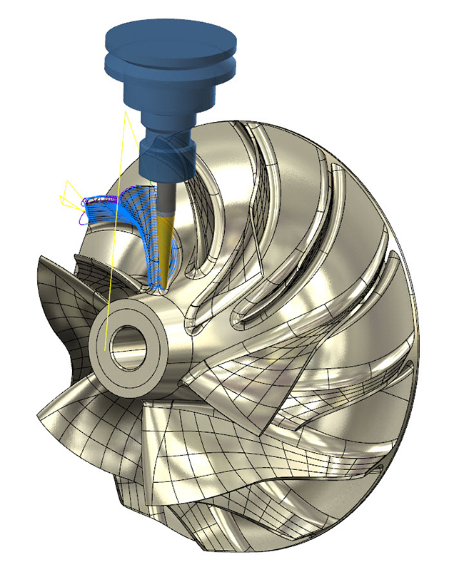
Before any machining can take place, the product must be completely, precisely, and accurately modeled. This is where CAD plays its role. CAD replaces the outdated manual drafting of 2D and 3D models, which was time-consuming and more prone to errors. Industrial designers use CAD to create renderings and vector-based drawings that culminate in 3D models that display the finished product’s size, shape, and texture.
The benefit in using CAD, other than the obvious time savings, is in the nearly limitless opportunities for modifications that don’t add any cost to a part. Programmers can experiment with proportions and materials and edges to truly optimize a part, all without having to waste material in prototyping. Additionally, models are no longer tied to physical copies that can be lost or damaged. CAD files can be multiplied and shared inexhaustibly. Many manufacturers share their files to the cloud so that employees and subcontractors can all access a file whenever they need to.
CAM 101
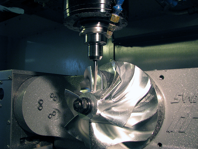
CAM controls the machines that produce parts and optimizes the production process altogether. Most commonly, CAM software is used with computer numerical control (CNC) machining centers by creating the G-code that drives their cutting activity. In the past, this G-code had to be painstakingly written by hand, but CAM systems automate this by translating digital models into detailed manufacturing instructions. These instructions can control a wide range of processes, including:
- Milling
- Lathing
- Routing
- Cutting
- Metal stamping
- Grinding
- Laser cutting
- Robotic actions
Consider a block of stainless steel that needs to be machined into a mold for an automotive manufacturer. A CAM system will allow its user to find the best way to mill away the stock material until just the desired mold is left. When the programmer chooses a software option to remove the first material, their CAM software will automatically program the roughing path that the cutting tool will follow, using information from the cutting tool and the machine itself. Although the user can modify and change this toolpath, the majority of the work has been done for them within seconds. Overall, CAM provides a simpler, more efficient way of manufacturing that reduces labor costs as well.
CAD and CAM Working Together
CAD and CAM software, while different, work best in tandem. CAD provides the information-dense digital models that a CAM system needs to program manufacturing. CAM writes intuitive G-code that in turn makes CAD models real. In the best-case scenario, the CAD and CAM software systems can interconnect seamlessly, with no lost data or glitches. This is why some developers offer combined CAD/CAM systems, like Mastercam CAD/CAM software. Using easily paired software – or software that comes already combined – is the key to quick, easy, and profitable manufacturing from design to finish.
For information on Mastercam products, please click below.


Leave A Comment