When considering analytic 2D and 3D features, Control X can return a lot of useful information from manufactured features on an aligned scan. For example, when considering cylinders (holes) in a manufactured part (3D Printed, machined, etc.), Geometry Deviation analysis can return essentially all of the pertinent data required for manufacturing in terms of measuring location, size, and orientation.
In the example of the gas valve below, the scan of the machined part was already aligned to its nominal CAD model. Shown below are the results when analyzing two cylinders on the part for size, location, and orientation.
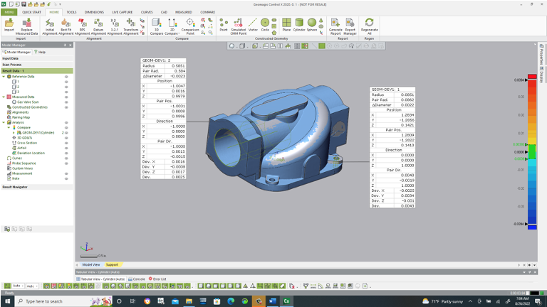
The “paired” values are provided from the scan and actual values are provided from the nominal CAD model. The deviation values show the centerline deviation of the scan to the nominal CAD model in the three directional axes as well as the “Dev” value, which is the ‘as-the-crow-flies’ deviation, from scan to CAD model.
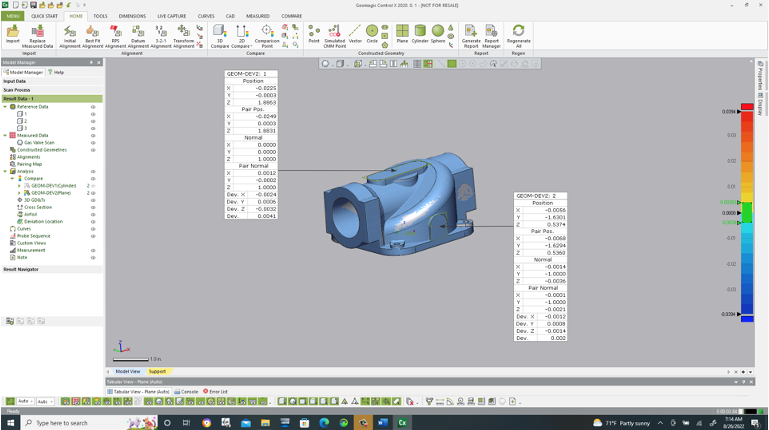
For planes, the compelling information provided in the Geometry Deviation analysis is the normal vector and how the scan differs from the nominal model.
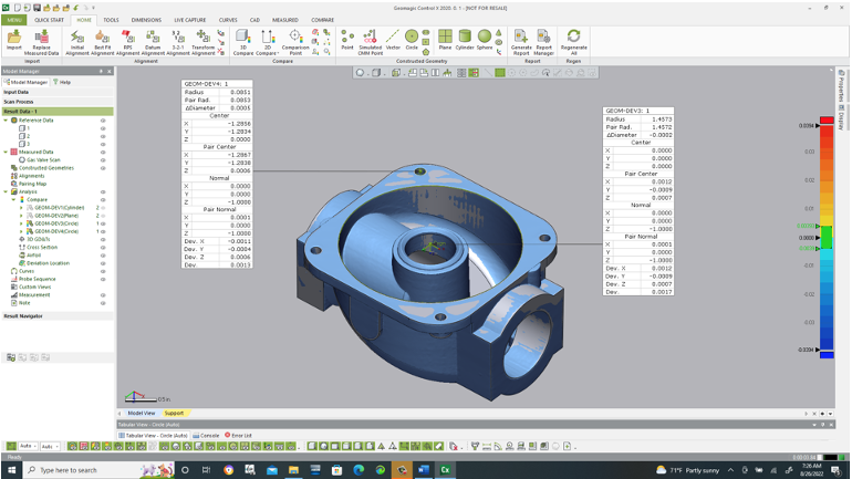
2D information is available as well through Geometry Deviation. The image below shows analyzing the scan of a circle on the part as compared to the nominal CAD model. While 3D Geometry Deviation is perhaps more beneficial, the fast analysis of 2D geometry can also be quite helpful for checking 2d feature size, orientation and location quickly.
Please contact Joel Pollet with any questions.


Leave A Comment