When should you perform 3D scanning?
As with other tech novelties, the unbridled enthusiasm for scanners makes it difficult to differentiate the hype from the valuable applications.
Should you decide to seek out the answer in the vast online wilderness, you’ll discover some interesting passion projects and creative feats of engineering. Scanning body parts and boats seems to be a particularly popular pastime!
Fun and games aside, the world of manufacturing faces growing demands: short lead times, narrow tolerances, measuring complex shapes in extreme environments (think suspended bridges!). Under such circumstances, the value of 3D scanning is clear.
3D Scanning for Inspection
In particular, anyone conducting an inspection is likely to benefit from scanning due to the large amount of data that scanners can gather, the accuracy of the measurements and its non-contact nature. Two great examples of this come from SCAN IT 3D, a 3D scanning service provider and Geomagic partner that is based in Germany and Switzerland.
SCAN IT 3D has worked on a range of scanning projects, from reverse engineering vintage car parts, scanning entire trains, to inspecting pipes and modeling heads… You name it, they’ve scanned it.
Out of this wealth of cases, we’re going to look at two examples that demonstrate how non-contact scanning makes a difference by allowing engineers to do measurements that would be either unfeasible or impossible with traditional tools.
3D Scanning a Steam Turbine
Steam turbines are sizeable pieces of machinery. Inspecting one with traditional tools would require transporting it to a measurement laboratory. Good luck with that!
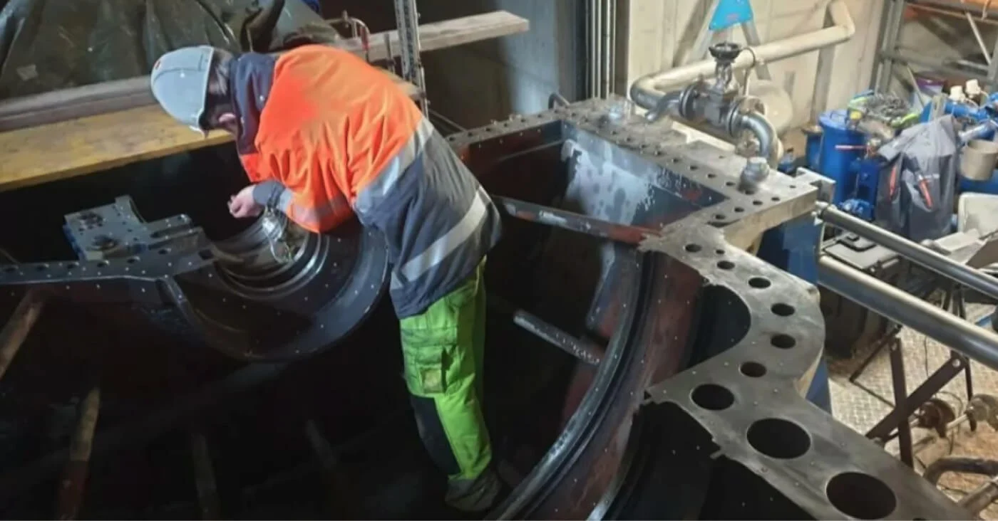
It’s in projects like these that 3D scanning clearly makes sense. When SCAN IT 3D was hired to examine a steam turbine housing, they immediately knew what approach to take. They decided to use a Creaform 3D scanner as it is portable and easy to use even in difficult situations, to reverse engineer the CAD model in Geomagic Design X, and to inspect the part with Geomagic Control X.
The process is simple. They scanned the steam turbine housing and opened the scan in Design X to create a 3D model which would be loaded into SOLIDWORKS to determine the position of the axial rings for bearings and blade carriers. The picture shows that the red rings were imported into SOLIDWORKS together with the 3D scan data. The positions were dimensioned using the dimensioning functions of SOLIDWORKS.
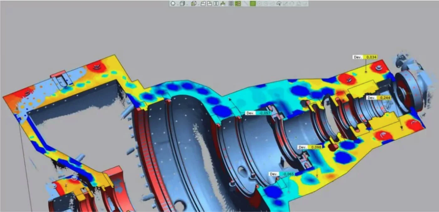
SCAN IT 3D also checked the flatness of the housing’s sealing surfaces. They created a flat surface in Design X and transferred it together with the scan data to Control X for quality assurance. The process revealed where the sealing surface deviates from the flat surface using a deviation colour map. The dark blue areas are holes, and the cyan and yellow areas are of interest in the evaluation.
Determining Wall Thickness of a Rocket Nozzle
Manufacturing processes such as rolling, pressing, or thermoforming involve changes to the shape of the piece as it is being created. This can lead to problems when you’re fabricating parts like rocket engine nozzles, where the thickness of the wall needs to be consistent across the entire workpiece.
If you want to check the wall thicknesses, using a tactile measuring machine is tricky, to say the least. The contactless nature of 3D scanning makes it a better-suited approach for this application.
A 3D scanner can capture the shape of the component. With Geomagic Control X, you can load the scan data and see the wall thickness in a deviation color map.
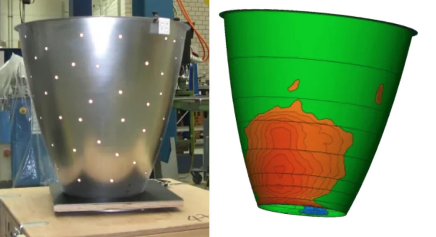
In SCAN IT 3D’s example above, you can see the areas where the wall thickness was less than the required one in red. The green areas are within the required tolerance.
By using the portable Creaform scanner, a preliminary statement can be made by recording the component on the machine in a clamped state and thus already identifying a trend.
When should you perform 3D scanning?




Leave A Comment