Selecting an appropriate 3D scanner for my inspection requirements
Selecting a scanner for non-contact inspection is a very similar process to selecting a new CNC machine or a new 3D Printer.
When shopping for a new CNC machine, users likely consider –
- Machine travel limits
- Controller/Programming capabilities
- Number of axes supported – Multi-axis capabilities (reducing setups)
- Feed and speed capabilities
- Horsepower
Similarly, when selecting a new 3D Printer, users likely consider –
- End use parts vs conceptual design
- Materials
- Part sizes
- Printer Maintenance requirements
- Accessibility of materials
While other parameters must also be considered when selecting a 3D scanner such as part sizes, there are two main parameters a user must consider.
- Accuracy
- Resolution (AKA – ‘Point Spacing’)
Accuracy
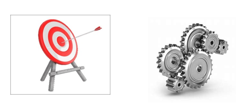
Any metrology-grade scanner must come with a “published accuracy” to provide users with confidence that their calibrated scanner will measure, at least, to the accuracy specs provided.
Accuracy is the easier of the parameters to understand. If you consider any scanner as throwing a bunch of points onto your part, the scanner’s accuracy is the +/- distance of those points to the actual surfaces they contact.
As a general rule of thumb, the accuracy of the scanner needs to be ‘better’ than your closest tolerances. So, for example, if your closest tolerances to check are +/-.005”, then ideally you will choose a 3D scanner that has a published accuracy of around +/-.001” to +/-.0005” (roughly 5 to 10 times “better” than your tightest tolerance requirements).
Resolution (Also Known As ‘Point Spacing’)
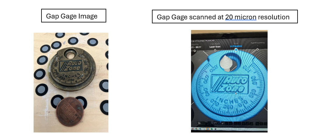
‘Resolution’ or ‘Point Spacing’ oftentimes gets confused with accuracy. But the two parameters are very different. I like to consider resolution as the density of the point cloud.
If the scan of a part appears to be melting, that generally means the resolution of the scanner wasn’t high enough, or there weren’t enough points captured to adequately represent the shape of the part.
If you consider this small, Auto Zone Gap Gage, the features are tiny and if the scanner’s resolution didn’t produce a dense enough point cloud, all of the engraving and embossing would be lost.
By using a scanner with a resolution of 20 microns, where no two points in the resultant point cloud are closer together than 20 microns (or .0008”), we can see that the scanned image captured contains most of the detail of the Gap Gage, although some is lost or ‘washed out’, such as in the Auto Zone logo.
Switching to a scanner with a 10 micron (or smaller) resolution (.0004”), the scanned image would be ‘crisper’ as the point cloud would be more dense. Conversely, if the resolution were 30 microns (.001”) or larger, the logo and details would be even more washed out.
So a lower number resolution gives a scanner the ability to capture more fine detail.
Let’s consider a more mechanical part.
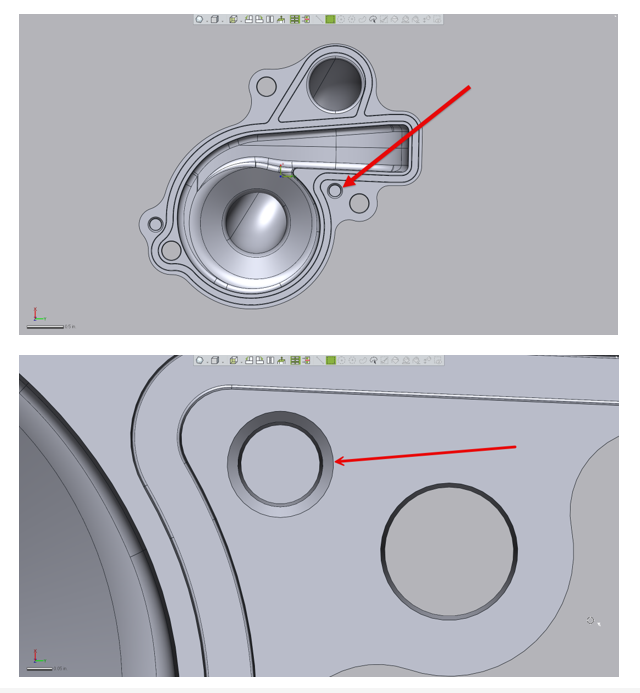
There is a hole in the mating surface of this water pump cover has a .010” countersink. So assuming the countersink need to be inspected, the scanner used in a non-contact inspection effort must then have a high enough resolution (i.e. a dense enough point cloud) to capture the chamfer’s shape.
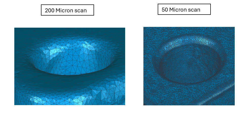
Below, we scan the mating face of the machined cover at both 200 microns and then at 50 microns and form a mesh,
Just looking at the point cloud would have been too messy to review, visually. But the triangular mesh clearly shows what happens when a scanner of low resolution us used to capture a tiny feature.
We notice at a 200 microns resolution (.008”) scan, the shape of the chamfer is completely ‘washed out’ and it actually ends up looking more like a radius. But at 50 microns (.002”), the point cloud is dense enough to clearly form the countersink well enough to then be measured.
This same type of analogy may be applied to 3D ball milling as well as 3D Printing.
If the stepover of the ball mill is too large, the resultant surface quality may not be suitable. So the CNC programmer considers the end use of the part and what scallop height will be acceptable and adjusts their toolpath accordingly.
Similarly, some types of 3D Printers have a ‘slice resolution’ which is essentially the thickness of printed layers. This thickness also determines which features will come out of the Printer clean and crisp vs ‘washed out’ in the final model.
So while the resolution of a 3D scanner is measured differently than how one measures a ball milled surface or a 3D Printed component, the principals are very similar. Resultant models must be able to capture the needed features of the part in order for inspection software to use the scan for measuring.


Leave A Comment