
New Tools for Safer, Cleaner, and Smarter Metal 3D Printing: Introducing the Dual Glovebox and XMSieve
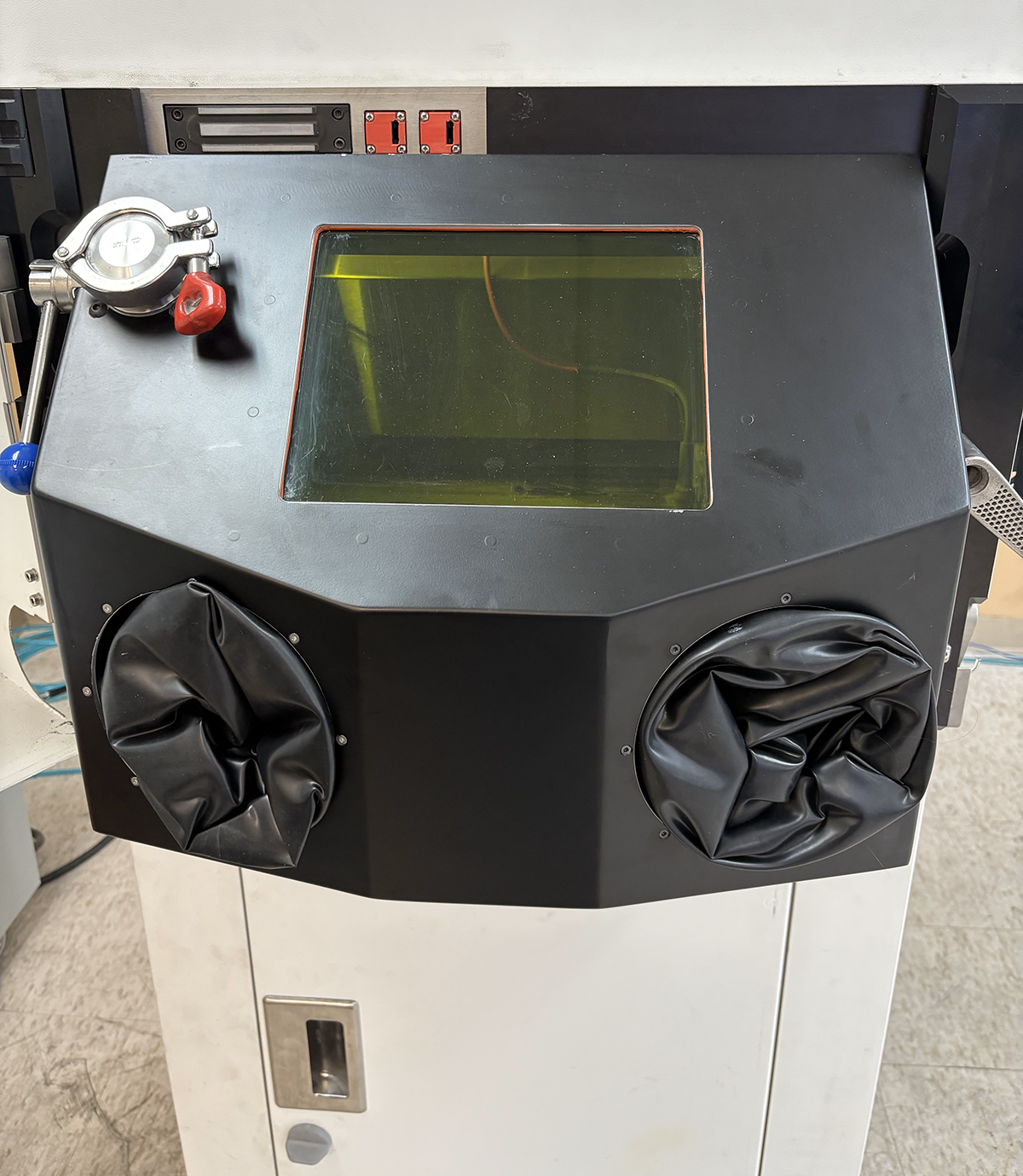
Managing metal powders in 3D printing environments just got a serious upgrade. Whether you’re focused on efficiency, safety, or print quality, these two new solutions from Xact Metal are designed to elevate your workflow. 🔧 Dual Glovebox: Smarter Powder Control Starts Here Replacing the older single-glovebox design, the new Dual Glovebox offers a major leap in functionality, ergonomics, and safety. Here’s what makes it stand out: Spacious Interior: A wide glovebox door provides easier access for handling powder and tools inside the chamber. Ergonomic Viewing Window: A large, centered viewing window gives operators clear visibility into the build chamber for more accurate and confident handling. Built-in Storage: Internal storage space keeps essential powder-handling tools and powder bottles within easy reach. Entry Port for Powder Addition: Powder can be added without opening the main printer door—especially valuable for oxygen-sensitive materials. The chamber can be purged before loading, maintaining a controlled environment. Safety Interlock System: To protect users, the system disables the laser and blower motor when the outer door is open. 🧪 XMSieve: Clean, Safe, and Efficient Powder Reclamation The XMSieve is purpose-built for non-reactive metal powders, allowing for quick, safe, and hands-free sieving. It [...]
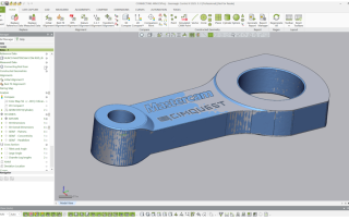
Batch Processing – Unmanned Inspections
We’ve seen how to inspect the scan of a single, manufactured part against an inspection plan generated using a nominal CAD model. But what if we have many manufactured part scans to inspect against the same inspection plan, using the same nominal CAD model. That’s where Batch Processing comes in. The exact same inspection process can be reused as many times as needed and no human intervention is required. Once the batch processing routine is complete, you will have date and time-stamped, serialized inspection reports for each unique part scan. The first step is to create the complete inspection model against the nominal CAD model and perhaps inserting the very first scan to verify alignment, data measurements and output to ensure everything that needs to be inspected is setup properly. The Batch Inspection menu is quite simple to work with… We first select all scans that need to be inspected. Select the Add Files and Browse to the folder where the scans of all the connecting arms are. Next, if there are multiple Results files defined in the Control X model, select the one you’d like to use for this inspection. Next, select the desired Output Options [...]
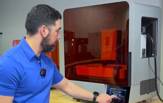
Meet the Formlabs 4L – Large-Format 3D Printing, Redefined
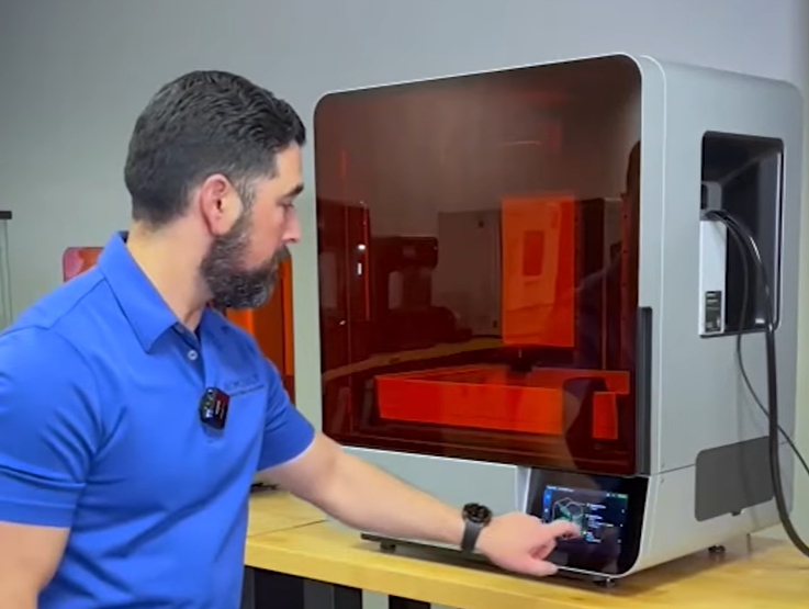
In the rapidly evolving world of 3D printing, Formlabs has consistently positioned itself at the forefront of innovation. Their latest offering, the Form 4L, exemplifies this commitment by delivering large-format 3D printing capabilities without compromising on precision or reliability. A recent YouTube Short by Cimquest provides a concise visual overview of the Form 4L in action, highlighting its impressive features and applications. Key Features of the Formlabs 4L: Large Build Volume: The Form 4L boasts a substantial build volume, allowing for the creation of larger parts or multiple smaller components in a single print run. This scalability is particularly beneficial for industries requiring rapid prototyping or the production of sizable end-use parts. High Resolution: Despite its larger size, the Form 4L maintains the high-resolution printing that Formlabs is known for, ensuring detailed and accurate prints suitable for both functional prototypes and intricate designs. User-Friendly Interface: Designed with the user in mind, the Form 4L features an intuitive interface that simplifies the printing process, making it accessible to both seasoned professionals and newcomers to 3D printing. Material Versatility: Compatible with a wide range of Formlabs resins, the Form 4L offers versatility across various applications, from engineering and manufacturing to healthcare and [...]
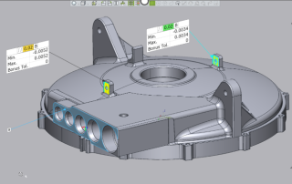
Color Mapping Fitting Deviation
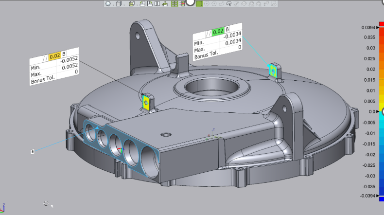
In each of the Control X GD&T commands, users have the ability to color map the Fitting Deviation. So when checking for Flatness, for example, along with being able to show the Min and Max deviations as we do in the examples below, users can actually color map those differences. Below we show that the flatness of this face is within its assigned Flatness tolerance of .002” as the Min and Max values are +/-.0008”. Please contact Joel Pollet (joel.pollet@cimquest-inc.com ) with any questions or to obtain additional information regarding Design X Go. But by turning on the Color Map Fitting Deviation Switch, we can actually see exactly how that tolerance is distributed, across the face. We can see that while the planar surface is within its Flatness requirement, we can also see by the yellow color (full or ‘oversize’ condition) that it bulges slightly in the center while being on the ‘low or undersize side’ (blue color) on the ends. From this information, we can possibly make changes to the CNC toolpath that machines this face or perhaps to the fixturing that holds the part during the machining process to produce an even flatter surface. Next we explore color map [...]
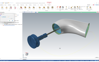
From an Engine Port to a Machinable Multi-Axis CNC Toolpath
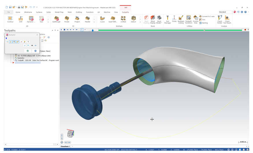
One of our customers was recently faced with the challenge of needing to machine a complex engine port shape without a CAD model, having a circular cross-section on one end, oval on the other and was bent 90 degrees Due to the bend, the port would also need to be machined, from both ends. Below is a cross section of a similar port with a porting cutter positioned to check the depth we could reach, from one side. It was clear that we would need to address the machining, from both ends. The solution would be to scan the port shape and to then use Design X Go to build a machinable model from the scan data. But that too would prove to be challenging due to the bend in the port. How would we scan this shape when our handheld scanner couldn’t ‘see’ the complete cavity…So we got creative! We added a partition and separated the port into two (2) sections. We then poured each mold section, let the material harden, pulled them both out and glued them together. This exercise provided us with a physical model of the port shape. But how do we now go from this physical [...]
3D Printing Applications for Defense Industries
This whitepaper by UltiMaker explores how 3D printing is revolutionizing defense operations by enabling rapid, cost-effective production of critical components, tools, and replacement parts. Through collaboration with armed forces, the paper highlights real-world applications where additive manufacturing improves operational readiness, reduces downtime, and cuts costs. Key Applications: FRISC Antenna Fixture – Replacing corroding aluminum parts with glass-fiber-reinforced nylon, ensuring durability in harsh naval conditions. Cost Savings: 84% Production Time Reduction: From 6 weeks to 20 hours Navy Cold Water Filter – A PLA and TPU 3D printed filter replacing corroding Inconel parts, saving the Dutch Navy €12,560 per ship annually. Cost Savings: 98% Production Time Reduction: From 2 months to 1 day Rotinor Turbine Wrench – Custom 3D printed carbon-filled PA tool for maintenance of underwater diving systems, replacing expensive steel wrenches. Cost Savings: 98% Production Time Reduction: From 12 weeks to 13 hours Radio/GPS Bracket – Lightweight carbon-fiber polyamide mount for secure attachment of communication devices on military vehicles. Cost Savings: 79% Production Time Reduction: From 4 weeks to 24 hours Gasoline Funnel Extension – Custom polypropylene funnel preventing fuel spillage and fire hazards, offering a flexible and field-ready solution. Cost: €5 Production Time: 6 hours EpiPen Casing – Rigid, durable [...]