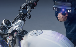
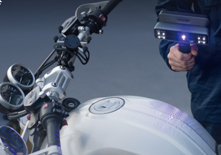
Introducing the Einscan Rigil from Shining 3D
The recently announced Einscan Rigil, from Shining 3D, is the world’s first tri-mode scanner that has a built-in computer, wireless connectivity and hybrid light technology. When tethered to a computer, the Rigil can scan in high accuracy, high precision laser mode without targets. But targets may also be used, when laser scanning, wirelessly. Using Targets - Wireless Target-free laser scanning mode! – Wired via USB Cable Additionally, in laser mode, the Rigil has 40 micron accuracy and a maximum resolution (aka ‘point spacing’) of 50 microns. It uses 38 laser crosses (19 X 19) and can also use 7 parallel laser line mode for high-definition scanning. So when fine detail needs to be captured, such as clear embossing, the 7-laser line mode is an excellent option! The Rigil also offers an Infrared mode for scanning, which is paired with two separate cameras to ensure versatile performance and excellent efficiency for the scanning of objects of varying sizes and surface types. The Rigil is truly 2 scanners in one! The Rigil has two separate groups of cameras and projectors that are specifically designed to utilize laser or infrared light to obtain optimal performance and scan [...]
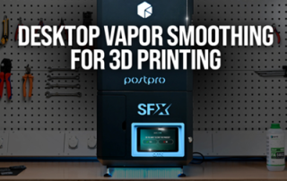
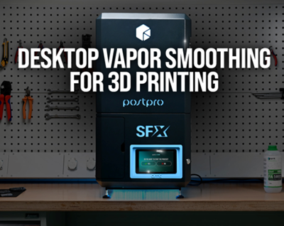
AMT PostPro SFX: Desktop Vapor Smoothing for 3D Printed Parts
AMT PostPro SFX: Desktop Vapor Smoothing for 3D Printed Parts 3D printed, unprocessed parts exhibit a rough and porous surface, which limits their use in various applications. To solve this issue, AMT PostPro developed its own patented vapor smoothing process to deliver 3D prints that are more durable with smoother and sealed surfaces. As part of their vapor smoothing product line, AMT has also developed a benchtop machine size. The PostPro SFX brings industrial vapor smoothing to a desktop-scale system. Why Choose the PostPro SFX for Vapor Smoothing? Designed for small-batch production, laboratories, and workshops, the SFX system delivers high-quality surface finishes on a range of thermoplastic parts made using SLS, MJF, SAF, HSS and high temperature FDM printing technologies. This vapor smoothing system is ideal for any manufacturer looking to scale their post-processing workflow gradually. The benefits include: Smooth and sealed surfaces for end-use 3D printed parts Compatible with a range of thermoplastics, including PA11, PA12, TPU, composites, and PEI. Supports materials printed with MJF, SLS, high temperature FDM, SAF, and HSS Uses our non-hazardous, biodegradable consumable, PostPro Pure Delivers repeatable, high-quality results in just under two hours It’s plug and play. The process is easy, and no [...]

Metrology Minute – 2D Inspection Drawing in Control X
2D Inspection Drawing in Control X While most dimensions and GD&T calculations in Control X will come from the 3D model, it is also possible to create 2D inspection drawings and to create Construction Features to assist in the process. Consider the highlighted face below. Suppose we want to build several 2D inspection dimensions in that face. We start out by telling Control X to create a 2D drawing in the plane of that face. As we zoom into an area, we can see both solid and dashed 2D geometry. The solid geometry represents the nominal CAD model’s cross section at that planar location while the dashed geometry represents the scan. Just from this image, we can tell that this hole’s Cylindricity is a bit off, even without measuring. Next, to measure the theoretical thickness at a location, we ask Control X to create Construction Points at the intersections of lines A&C and B&C. Now that the theoretical intersections are in the inspection drawing, we can ask Control X to measure the distance between the two points, representing the part thickness. Next, Let’s measure from the center of the main port to the outer tangency radius, shown [...]
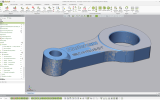
Performing a Datum Alignment using Control X
Performing a Datum Alignment using Control X Before the scan of a manufactured part can be inspected using Control X, it must first be aligned to its nominal CAD model. The nominal CAD model represents the ‘perfect’ shape. Once aligned, all of the Control X inspection functions, including Color maps, Whisker plots, 2D and 3D dimensions, Geometry Deviation, 2D Twist Analysis and more can all take place. Consider the water pump cover shown below, prior to alignment. The datums to be used for alignment can all be found on the mating side of the cover. The Primary Datum, Datum A, is the mating face on the underside of the cover. Datum B is the large cylinder and datum C is the small hole that will clock the alignment. The datum Alignment tool makes simple work of aligning the scan to the nominal CAD model by matching up the analytic features that were selected as datums on the nominal CAD model. The software can distinguish the matching features on the scan and perform the alignment with three simple clicks on each datum surface. After alignment, the software returns any alignment error for the Primary, Secondary and Tertiary datums. Once aligned, any [...]
How Flat is Flat Enough? – Verifying Flatness of a CNC Face-Milled Surface
Let’s say that this water pump cover needs to lie flat against its mating surface to within a specific GD&T Flatness Callout. We’ve seen, in the past, that Control X can check for GD&T Callout information and return pass/fail conditions. But we can also use Control X to determine the amount that a part is in or out of a ‘Flatness’ spec by turning on a localized color map that we call a ‘Fitting Deviation’. Let’s consider the flat (blue) surface on the water pump cover and ask Control X to check Flatness of the face to .040”. We see that the Flatness of the face is well within the Flatness tolerance callout. The actual flatness is actually coming out at .0176”. Since the Flatness callout displays a total tolerance value, we can turn on the +/- values to display the Max and Min values. Next, to really examine our surface of interest, we turn on the Fitting Deviation, color mapping tool and can get a much better sense as to exactly what is happening to the face during the face milling operation. Understanding the color map can be extremely helpful for optimizing your toolpath. Below, we notice that the [...]
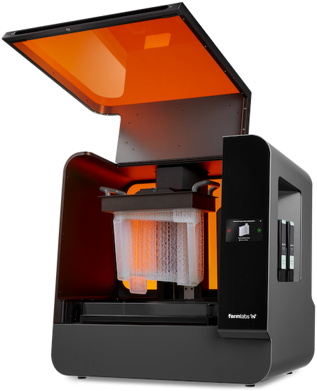
Special Offer: 3D Printer Demo Units Available!
Special Offer: 3D Printer Demo Units Available! At Cimquest, we are committed to providing you with the latest advancements in 3D printing technology. To make space for our new models, we are offering several demo units of our 3D printers at unbeatable prices. This is a fantastic opportunity for anyone looking to enhance their 3D printing capabilities with high-quality machines. Formlabs Form 3L Demo Unit To make room for the new Formlabs Form 4L, we are offering our Formlabs Form 3L demo unit for sale. The Form 3L has been a reliable and efficient machine, consistently delivering high-quality prints with exceptional performance. Key features include: Large Build Volume: Ideal for large prototypes and detailed models. Intuitive Workflow: User-friendly operation with automatic resin dispensing and simple print preparation software. High-Quality Prints: Produces smooth surface finishes and fine details. UltiMaker S7 Demo Unit We are also offering our UltiMaker S7 demo unit for sale to make room for the brand new UltiMaker S8 Pro. The UltiMaker S7 is known for its versatility and precision, making it a favorite among professionals. Key features include: Advanced Print Capabilities: Supports a wide range of materials and complex geometries. Reliable Performance: Consistent and accurate prints with minimal downtime. User-Friendly [...]