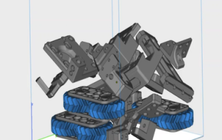
Materialise Magics – Packing Programs for 3D Printing
Let’s take a look at how to incorporate 3D packing software into your plastic powder workflow. While most machines come with their own packing programs, Materialise Magics can be a fantastic addition to your process. In this post, we’ll explore an example of a build for Formlabs, XYZprinting, and HP plastic powder printers that were packed in Magics. Magics is a mesh manipulation software that specializes in 3D packing. The program uses the geometry of your model to efficiently pack your parts, whereas other programs simply use the bounding box of your models. Due to this, Magics is able to increase the packing density of your builds, reducing the overall waste material that you generate and the time needed for printing. The first thing you need to do is import some files into the program. Magics can interpret almost every 3D file type including STL, 3MF, STEP, Solidworks, Creo, Inventor, and other native CAD files. When using STL files, you will need to confirm the sizes of your parts, since the file type holds limited information on the units. Using the handy scaling tool, you can convert between millimeters and inches with the click of a button. After importing, the next step is [...]

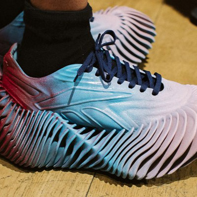
Concept 3D-Printed Sneaker Made of One-Piece Construction
(Article reprint from AdditiveManufacturing.com) A new concept sneaker revealed at Paris Fashion Week makes use of 3D printed TPU not just for the sole, but the entire body of the shoe — a consolidation that hints at how additive manufacturing might further streamline footwear production in the future. The Reebok × Botter shoe was engineered with the HP 3D printing team based in Barcelona and manufactured using the latter’s Multi Jet Fusion technology. Reebok x Botter Concept Sneaker Engineered by HP premiered at the 2023 Paris Fashion Week. Photo Credit: HP Inc. Taking design inspiration from the shell of the predatory murex snail, the shoe features a distinctly ridged sole and a laced upper. The pairs showcased at Fashion Week were hand-painted to complement the colors of the Caribbean Sea found throughout Botter’s FW23 collection. Read the Full Article
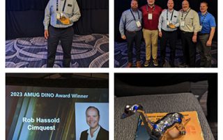
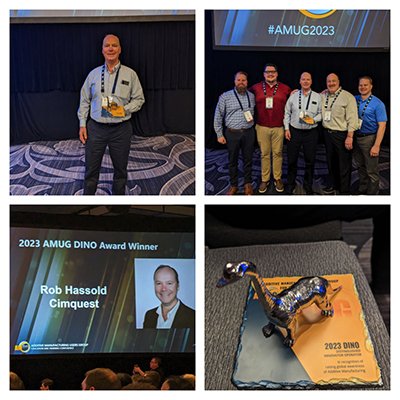
Our CEO Wins the Distinguished INnovator Operators Award (DINO)
Congratulations to Rob Hassold, our CEO, for winning the DINO Award at AMUG2023 The DINO Award is AMUG’s most prestigious honor and is bestowed upon those with the highest levels of additive manufacturing expertise as well as a willingness to share that knowledge through contributions to AMUG, its members and the industry it represents. Each year, the DINO Selection Committee reviews submitted nominations and the list of conference registrants to select no more than 10 deserving individuals. The committee considers contributions to AMUG (speaker, volunteer, etc.); contributions to the AM industry; years of hands-on work with an AM technology; willingness to share and assist; skill level; and other subjective factors. Over AMUG's 35-year history, only 177 individuals have been awarded DINOs. We are very proud to be at the forefront of the Additive Manufacturing industry with a DINO award winner at our helm. Congratulations Rob!
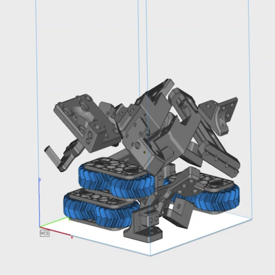
Lockheed Martin to Use Makerbot 3D Printers For Their Next Space Project
Lockheed Martin Space uses METHOD X to create parts for the lunar rover project, enabling the engineers to design, develop, and test autonomous systems and processes Lockheed Martin is a global aerospace and defense company, with the mission to connect, protect and explore. The company focuses on next-generation and generation-after-next technologies. In alliance with General Motors, Lockheed Martin is developing a new fully-autonomous lunar rover that could be used for NASA’s Artemis program. This is a fitting team that pays homage to the original Apollo rover, which GM was also involved in its development. Some elements of the rover’s autonomy system’s early design and development is done at Lockheed Martin’s state-of-the art R&D facility in Palo Alto, Calif., the Advanced Technology Center (ATC), which is well-equipped with a variety of cutting-edge technology, including a lab full of 3D printers. MakerBot 3D printers have been in use for about five years and have provided easily accessible 3D printing for a host of projects for Lockheed Martin’s team of engineers. Lockheed Martin's Advanced Technology Center is a major hub for developing next-generation space technology. ULA rockets commonly carry space-going payloads like the satellites being developed at the ATC. “A lot of [...]

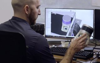
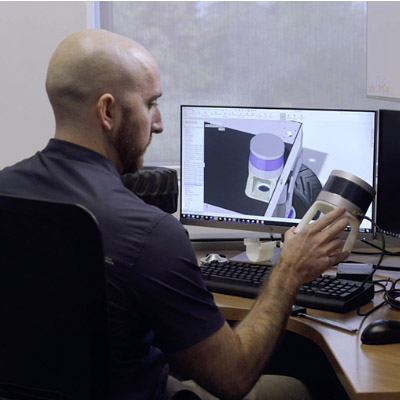
Metrology Minute – Control X Measure Menu
While most users of Control X are interested in producing color maps, whisker plots, dimension checks, and GD&T analysis of the scan as compared to the nominal CAD model, it is important to note that there are several “mesh-only” functions for measuring a scan model that do not require a nominal CAD model. The Measure Distance menu simply measures the distance between two points. You just need to keep in mind that the distances are generated from the nearest vertex points on the mesh, not the actual selected point. The Measure Angle menu will measure the angle between two mesh faces, such as the chamfer and body scan below. The Measure Radius menu simply measures the radius of a mesh by selecting three points. The Measure Area menu measures the surface area of the selected mesh. This measurement is in terms of units squared (for example, in^2, mm^2, etc.). Surface area calculations may be for both closed and open mesh files. The Measure Volume menu measures the volume of a fully closed, manifold mesh. The units are in terms of cubic units (i.e. MM^3, In^3, and so on). The term “closed manifold” implies every triangle edge in the mesh shares one and only [...]
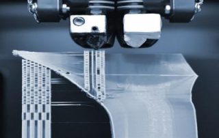
3D Printing Surged 23% Last Year
3D Printing has surged 23% in 2022 and is now a $13.5 billion industry. (A reprint from DesignNews) Photo courtesy of Design News. The fourth quarter of 2022 capped a strong year for additive manufacturing markets, according to SmarTech Analysis. Even in the face of uncertain economic conditions, the growth rate for all 3D printing hardware, materials, software, and services expand by 23% in 2022. The year-end spending on additive manufacturing hit $13.5 billion. Sectors in the industry expanded at different rates. The metals market grew 25%, to $4.9 billion, while the polymers market grew 20%, to $7.3 billion. The software segment reached $1.2 billion, and the additive manufacturing services totaled $6.0 billion. Sector-by-Sector Growth The big movers in additive adoption continued to be aerospace and dental. In both industries, 3D printing has morphed into a matured manufacturing process. Yet other sectors are now showing strong growth. “Though the aerospace industry drove growth in additive manufacturing over the last decade, followed by medical/dental, other sectors are starting to catch up with growing adoption, particularly leading up to and after COVID hit,” Michael Molitch-Hou, editor-in-chief of 3DPrint.com, told Design News. “Specifically, automotive and, more recently, oil and gas, have been using the [...]