Casting Metal Parts for Prototyping from 3D Prints
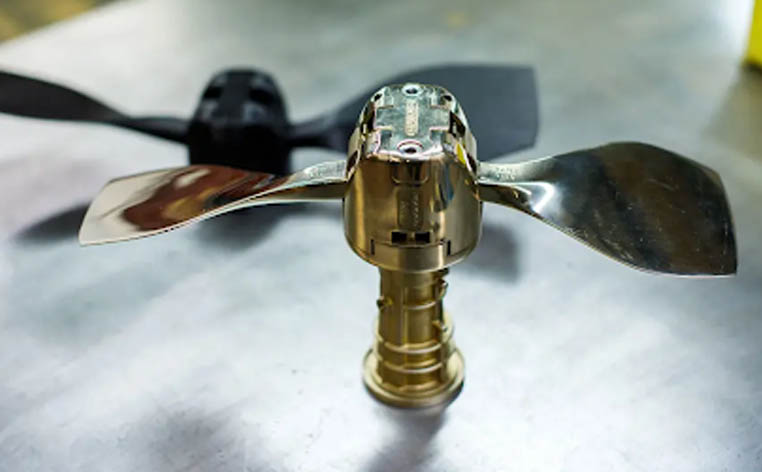
Sylatech is an investment casting firm that uses Ultimaker 3D printers to speed up their rapid prototyping process. Sylatech offers services in CNC machining, radio frequency and microwave manufacturing, and investment casting. They have been around for over 53 years and have customers in aerospace, space, defense, medical, automotive, and construction. Sylatech uses 3D printing as part of their investment casting process. Before using Ultimaker 3D printers, customers had to directly invest in tooling needed for making their specific design in metal. However, if their metal part needs modifications, this can become a time consuming and costly addition to the process. Using an Ultimaker, the prototype can be finalized before investing in tooling for larger volume productions, cutting the risk of such changes. Speeding up the prototyping process With Ultimaker 3D printers, Sylatech can create a 3D printed model of the customer's design in a matter of days. These are then directly used to create a metal prototype. When modifications are needed to the design, the only additional cost is to 3D print the updated design. The 3D printed part made from PLA already gives an accurate prototype before a single metal part is created. When the 3D print is accepted, the metal [...]
New Partnership with MakerBot
We are proud to announce a partnership with MakerBot. Founded in 2009, MakerBot brought one of the first mass-produced and readily available 3D printers to the market which earned their acquisition from Stratasys®, a leader in industrial FDM 3D printing. In recent years, MakerBot as a company has completely transformed their business with a new focus on the B2B market. This becomes apparent when you see that the METHOD Series 3D printers have 21 industrial 3D printing patents from Stratasys® including: 100°C heated chamber Part dimensional accuracy ± 0.2mm (± 0.007in) Stratasys® SR30 Support Material Compatible with all 3rd party filament Nylon 12 Carbon Fiber, PC ABS, ASA and many more... To kick things off, Cimquest is running a promotion with MakerBot. Click below to claim a 25% discount on the Method Series. Claim the discount
New Dates for Xpand3D Manufacturing and Design Event
The xpand3D event will take place virtually April 20 & 21 We decided to push this virtual event off by a couple of months. We have been busy gathering content and we know that the further we push it off, the more great content we will be able to provide. Also, given the fact that Covid is going to prevent the previously scheduled spring in-person trade shows, this virtual gathering will nicely fill the gap in manufacturing events. At this virtual event you will have the opportunity to learn about the latest developments in 3D Printing, CNC Programming & Machining, 3D Scanning, Inspection and more with our . . . Integrated Live Streaming All of our keynote presentations will be live-streamed and you will be able to watch them in real-time. With over 20 exhibitors on individual Live Streams, you can engage directly with specialists through the Live Chat and explore the latest tech. Educational Sessions and Panels Take a deep dive into various disciplines and gain insight into real-world practices through a variety of different breakout sessions. We set strict requirements and review all presentations prior to the event, ensuring that all content is primarily educational and not product-focused. There will be [...]
The Importance of Scan Alignment to Nominal CAD Model for Inspection
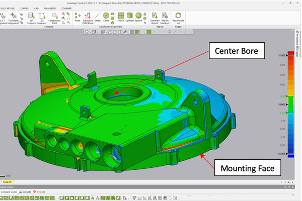
While many tend to use Best Fit alignments for inspection, the truth is that the alignment method may not provide the most accurate inspection results. When using a Best Fit alignment process, you are relying on the inspection software to understand the design intent and align the scan of the manufactured part properly to the nominal CAD model. If datums aren’t provided to use for alignment by the inspection drawing or PMI model, you would probably want to take some of the tightest or most critical dimensioned features and tie them into the inspection alignment criteria as their size and/or location would prove critical for fit and function of the final assembly. For example, among the most critical dimensions for assembling of the example cover below are the center bore and the mounting face on the bottom of the cover. The center bore is perhaps the single most important feature to have in the correct location and size to ensure proper symmetry and operation of the final assembly. A flush fit of the mounting face is nearly as critical to ensure a proper location of the cover along the centerline bore axis. Of slightly less importance is the one angled mounting tab (near [...]
ZEISS 3D Printing Precision Parts for Serial Production
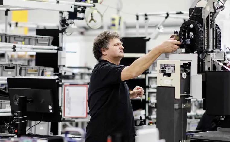
For Carl Zeiss Optical Components, a subsidiary of Carl Zeiss Industrielle Messtechnik GmbH, precision matters – sometimes down to the hundredth of a millimeter. The company manufactures microscopes, multi-sensoric machines, and optical sensors for industrial measurement and quality assurance purposes. Organizations around the world use ZEISS machines to confirm that they produce literally perfect results, every time. That means 'reliability' and 'repeatability' are words to live by at the Wangen, Germany-based company. "The machines we produce are very accurate. Therefore, there is a lot of know-how in the assembly of those machines," Johannes Grimm, Manager Operational Excellence at ZEISS, said. Aligned, stable, successful Each machine that ZEISS produces is built to align light to optical measurement axes. This alignment is created with brackets and adjustment screws. Each machine, however, requires a different alignment, which meant the ZEISS Team had to complete the work manually. A ZEISS employee works with an industrial microscope “This is not a very stable process, and that’s a problem for us. We were looking for a better solution, and found that solution in 3D printing,” Johannes said. By measuring the angles in a specific machine, the ZEISS team can design and 3D print an adapter plate, which [...]
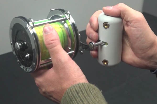
Reverse Engineering a Fishing Reel to Improve Ergonomics
Let’s take a look at how reverse engineering can be used to improve ergonomics in product design. There are times when you may have the need to improve a design, but the legacy files are not available. In this case, your best option is to scan the old part and reverse engineer the CAD file. Once you have a feature-based CAD file, you can make any edits and improvements needed. That is exactly what our application engineer, Hayati Dirim, did after fighting for 45 minutes with a 70lb tuna on a recent fishing trip. He found the handle of his PENN Senator reel to be too small and difficult to work with, due to an uncomfortable grip. Rather than buying a new reel, he decided to reverse engineer it to improve the design. He first scanned the handle portion with a Freescan X7 and cleaned up the Mesh file. Then he used Design X to create a NURBS model of the actual handle and used that geometry to design a new handle on top of it. The idea was to have the handle snap over the existing design and secure it with quarter 20 heat-set inserts. Lastly, he 3D printed a prototype on [...]