While many tend to use Best Fit alignments for inspection, the truth is that the alignment method may not provide the most accurate inspection results. When using a Best Fit alignment process, you are relying on the inspection software to understand the design intent and align the scan of the manufactured part properly to the nominal CAD model. If datums aren’t provided to use for alignment by the inspection drawing or PMI model, you would probably want to take some of the tightest or most critical dimensioned features and tie them into the inspection alignment criteria as their size and/or location would prove critical for fit and function of the final assembly.
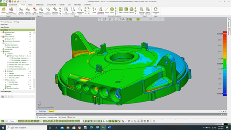
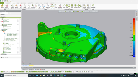
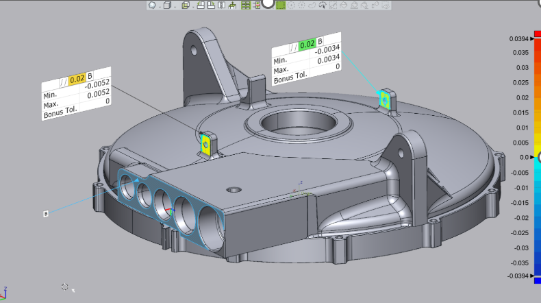
For example, among the most critical dimensions for assembling of the example cover below are the center bore and the mounting face on the bottom of the cover. The center bore is perhaps the single most important feature to have in the correct location and size to ensure proper symmetry and operation of the final assembly.
A flush fit of the mounting face is nearly as critical to ensure a proper location of the cover along the centerline bore axis.
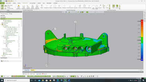
Of slightly less importance is the one angled mounting tab (near the connecting wedge) to fasten the cover properly in the final assembly. The hole location and size may be of importance as well. Again, knowledge of the final design intent becomes critical when selecting the alignment features.
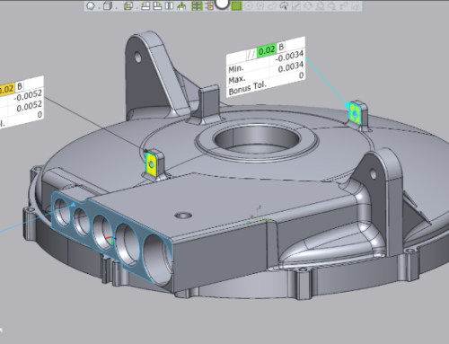
Since the center bore alignment is likely the most critical dimension to hold, a reasonable Datum structure might be for the bore to be declared Datum A, with the mounting face on the bottom as Datum B and the one mounting hole as Datums C.
By selecting the datums in this order, we are giving the highest priority to datum A and when datum B is being tested by the alignment software algorithm, Control X will ensure datum A’s size and locations are not compromised. Additionally, when datum C is checked for proper alignment, its feature size and location will not compromise the fit established by datum B.
So more than likely, datum A will have a very small to virtually no alignment error whereas datum B is affected by datum A and likewise datum C is affected by datum B.
Unlike constraining an assembly in a CAD system where the final alignments are ‘perfect’, these datums do not yield ‘perfect’ fits. Each subsequent alignment beyond datum A will introduce some level of error into the alignment process as manufactured parts are never ‘perfect’.
Please contact Joel Pollet with any questions or comments by clicking the button below.


Leave A Comment