Repositioning a Crankshaft in Control X
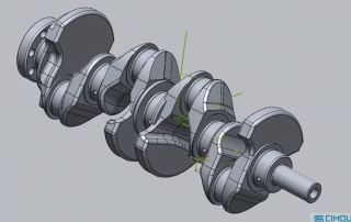
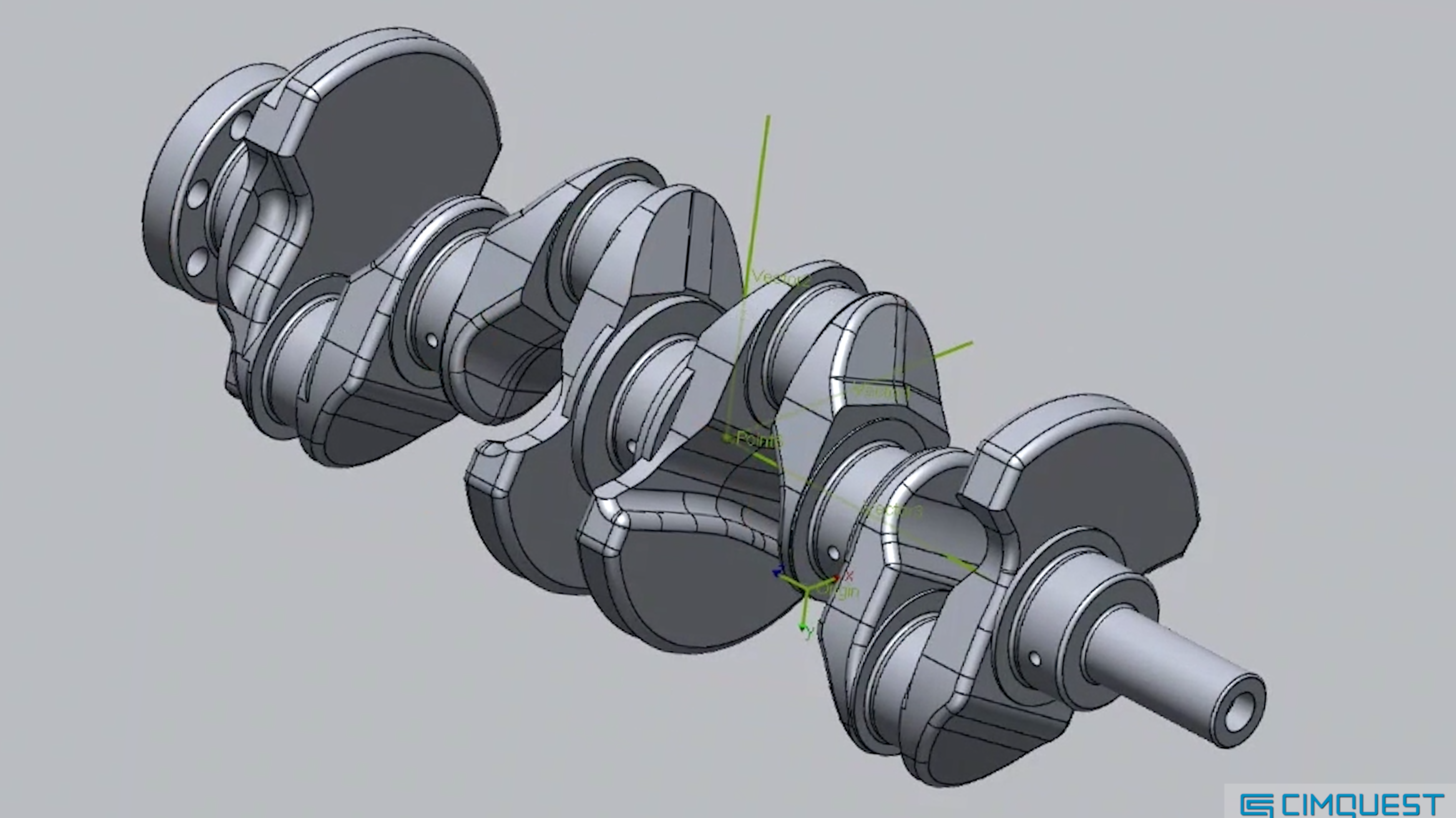
Repositioning a Crankshaft in Control X In this blog post, we’ll explore how to reposition the nominal CAD model in Oqton’s Control X so that inspection information is reported based on the main assembly’s coordinate system rather than the local subassembly. We’ll use a crankshaft as our example. Introduction to Crankshafts Crankshafts are essential components in piston engines, converting reciprocating motion into rotational motion. Before diving into the repositioning process, it’s advisable to reposition the model before aligning the scan and adding any inspection criteria. Model of a crankshaft. Why Reposition? CAD designers often create subassemblies like this crankshaft at a convenient location. However, when it’s time to report inspection information, it’s usually preferred to have the data based on the coordinate system of the entire vehicle or assembly, not just the local subassembly. Subassembly of a crankshaft at a convenient location. The Repositioning Process Control X offers several options for relocating the reference model. Today, we’ll focus on the Transform Body tool using an Interactive alignment. This method allows us to specify the new location and orientation using two vectors and a new origin point. Original and New Positions: On the left pane, the part is shown in [...]
Print a Model Every 49 Seconds with Fast Model Resin From Formlabs
Print a Model Every 49 Seconds with Fast Model Resin From Formlabs The Form 4B 3D printer and Fast Model Resin revolutionize dental printing by enabling the production of 11 models in just nine minutes. This combination optimizes speed without compromising accuracy, enhancing workflow efficiency and maintaining high mechanical performance. Fast Model Resin stands out with its improved aesthetics, offering a more opaque and matte finish compared to Draft Resin. It’s ideal for thermoforming applications, balancing speed and accuracy to ensure appliances fit patients correctly. The resin supports continuous printing, producing over 60 arches per hour with efficient post-processing. PreForm Dental software allows users to customize layer heights and printer settings, balancing accuracy, resolution, and speed. For detailed cases, a 100 μm layer height captures critical details, while the 160 μm Fast Arch setting is optimal for aligners. Dental professionals have successfully used these settings to achieve desired speed and accuracy. Feedback from professionals highlights the resin’s utility in both dental labs and practices. It supports same-visit dentistry and efficient production of aligners, with quick post-processing times enhancing workflow efficiency. Fast Model Resin’s superior mechanical properties make it a preferred choice for thermoforming models. Want to learn more about Formlabs Materials? Contact us below: Contact Us This abridged article [...]

Design X Reverse Engineering Options for Any Budget
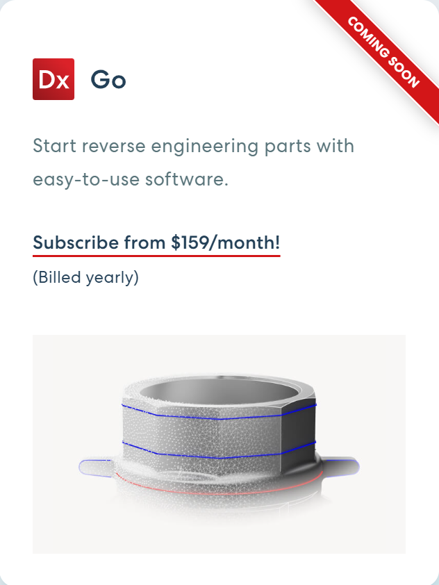
Geomagic Design X, known for its powerful features and scanner integration, is now more accessible with a three-tiered plan starting at $1,900 a year. These plans cater to various needs and budgets, helping new users start reverse engineering projects and upgrade as needed. Here's an outline of each: Geomagic Design X Go A new product plan for beginners in 3D scan-based reverse engineering or simple parts, starting at $1,900/year. It includes essential tools for modeling, mesh, and point cloud editing. Ideal for handheld scanners, it offers CAD software interoperability with Live Transfer. Design X Go Geomagic Design X Plus Routinely reverse engineering complex parts? You could speed up your workflow with the Plus plan’s enhanced tools for mesh control, modeling, surfacing, and accuracy analysis. Capture scan data directly in Design X with scanner plugins and probing tools. Design X Plus Geomagic Design X Pro Want to reverse engineer without limits? Design X Pro is the solution. Its toolkit lets you go from scan to CAD faster than anything else. Advanced tools for modeling, mesh processing, and surfacing allow you to create complex models. Automate workflows for similar parts with scan and batch processing tools. Modeling Wizards and Auto [...]
The newest Factor 4 material: Industrial 3D printing with PPS CF
The newest Factor 4 material: Industrial 3D printing with PPS CF Introducing the latest innovation in industrial 3D printing: UltiMaker PPS CF. This cutting-edge material is reinforced with 10% carbon fiber, which significantly enhances its chemical resistance, heat resistance, and dimensional stability. These properties make it an ideal choice for demanding applications in the automotive, aerospace, and defense industries, where parts are often exposed to harsh environments and high temperatures. UltiMaker PPS CF stands out as a cost-effective alternative to high-end metals and PEEK, offering substantial benefits such as lightweighting, reduced material waste, and increased design freedom. This material not only helps in creating durable and efficient components but also contributes to more sustainable manufacturing practices. One of the key advantages of UltiMaker PPS CF is its compatibility with the UltiMaker Factor 4 and print core HT. This ensures precise and reliable 3D printing results, allowing professionals to achieve high-quality outputs consistently. The material’s robustness and versatility make it suitable for producing a wide range of parts, from functional prototypes to end-use components. Whether you’re working on automotive parts that need to withstand corrosive substances or aerospace components that must endure extreme temperatures, UltiMaker PPS CF provides the performance and reliability required [...]

Metrology Minute – Utilizing Color Maps for understanding machining outcomes
Utilizing Color Maps for understanding machining outcomes Consider this airfoil. It was programmed and machined on a 5-Axis mill, using a single setup. The ball mill was able to travel completely around the shape, during the machining process and therefore blending the top and bottom of the surface didn’t need to be considered. Our job is to inspect the airfoil and make suggestions to the CNC Programmer and Tool Designer to optimize the machining process. So, the first step is to review a color map of the machined part as compared to the nominal CAD model to see where we start losing tolerance. The image below shows the datum alignment of the machined part’s scan to the nominal CAD model. Once aligned, our color mapping analysis can commence. Using Control X, we generate a color map, using a Specific (nominal) Tolerance of +/-.010” and a Min and Max Range of +/-.025”. The green geometry shown in the color map are areas of the model that fall within our acceptable tolerance band. But those areas that are trending to yellow/orange/red fall somewhere between +.010” and +.025”. We can see from the image above that the forward section of the blade is trending [...]
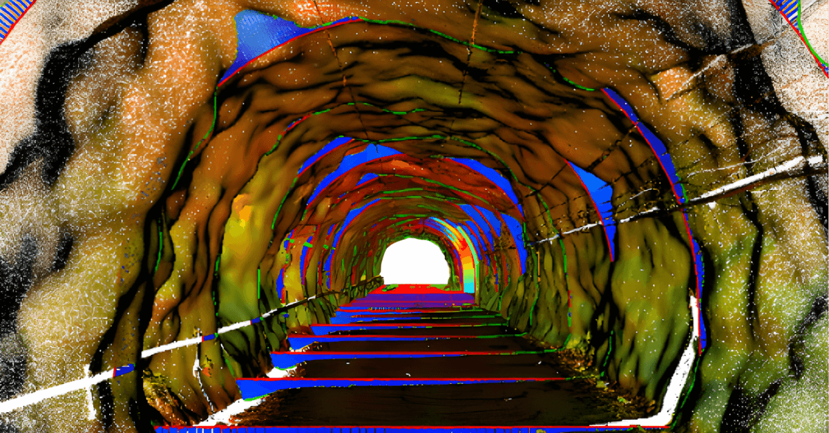
How 3D Scanning Can Be Used in Mining
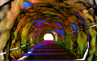
Miners face dangerous environments, extreme locations, and fluctuating demand. Efficiency and safety are top priorities, and 3D scanning technology may help achieve these goals. It redefines data acquisition for tunnels, shafts, stockpiles, and mills by offering speed and accuracy. 3D scanning is more efficient than traditional methods, capturing more data in less time with minimal disruption. It uses non-contact methods to gather data from risky or hard-to-reach areas, enhancing safety. 3D scan of an underground tunnel. 3D scanning software facilitates data processing for various applications like wear analysis, volumetric load scanning, spatial visualization, and reverse engineering. Exploring its advantages may help you understand the benefits for your mining operation. Efficiency With 3D scanning, mining companies can acquire accurate information about operations up to 10 times faster. They can map tunnel profiles, stockpile volumes, pits, and caves in minutes without much expertise. The digital data set can be accessed and analyzed later, reducing interruptions and downtime. Sectioning, a time-consuming surveying process, can be done in minutes with 3D scanning, allowing surveyors to produce thousands of sections quickly. Accuracy 3D scanners capture millions of data points to create precise 3D models of mine locations and equipment, improving accuracy over original plans. These scans [...]