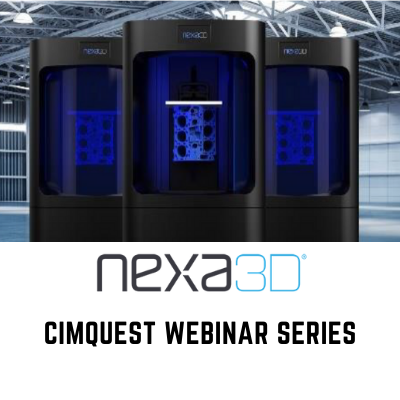
Learn about Nexa3D & Print in Real Time
Learn about Nexa3D & Print in Real Time Nexa3D printers are among the fastest in the marketplace, but how exactly does this technology work? In this webinar we will examine the logistics, overview the technology as a whole, and lastly print a build in real-time. Join us as we delve into the mechanics of Nexa3D https://cimquesttv.wistia.com/medias/u877n27358?embedType=async&videoFoam=true&videoWidth=640
Machine Data Collection with Cimco
Machine Data Collection with Cimco - Webinars on Demand In this last chapter of this webinar series we will provide another substantial function to implement on your day to day use of the Cimco product.We will challenge you to learn the functions of Machine Data Collection (MDC) to collect shop floor information such as cycle start/stop, feed/speed overrides, etc. We will implement the use of MDC Ports to collect the data and MDC Clients to utilize the data by either displaying ‘live’ information on TV monitors strategically placed on the shop floor or in reporting. We’ll integrate the FUTURE by allowing Web Clients to enable the use of devices like Tablets, both for remote access, as well as providing a portable method to enter and view information. https://cimquesttv.wistia.com/medias/i80pscuvgl?embedType=async&videoFoam=true&videoWidth=640
Supply Chain Disruptions – Bringing Your Sourcing In-house
By George Sigouros, Account Executive Today, as we review our place in a new world order, it now features the pandemic crisis and a significant disruption in the global supply chain. Who knew we would be forced to evaluate our strategy and use additive manufacturing to in-source. As demonstrated by the global spread of the virus, combined with the life-saving response of the additive manufacturing community, clearly this has changed the way we do business. As medical teams struggle to cope with the reality of this global pandemic and work diligently to secure medical supplies, the crisis and the supply chain disruption has impacted the healthcare system and its ability to save lives. Now more than ever it is incumbent on us as a community to ensure that the medical teams have what they need to battle this crisis. The acceleration of producing medical parts and products, and not being dependent on outsourced manufacturing, is the new reality. With its ability to instantly adapt, additive manufacturing can deliver parts into a disrupted supply chain and be the life preserver that our community needs. This has brought new awareness and renewed value to the ability and strength of our industry. Insourcing and using 3D [...]
Inspection Automation and Batch Inspection Webinar
Inspection Automation and Batch Inspection Webinar In this webinar on demand we demonstrate how Batch processing in Control X can be used to create one inspection process that can be applied to multiple parts and or scans automatically with the advantageous component of it being an unmanned process. Watch as we uncover how to develop a singular Control X inspection program then capitalize on it by using it for any other subsequent inspections. https://cimquesttv.wistia.com/medias/d9q76g6l6h?embedType=async&videoFoam=true&videoWidth=640
Additive Manufacturing in Color
With all the new 3D printing technologies coming to the Additive Manufacturing market, one can be flooded with options and confusion. - monochrome, full color, materials, functionality, prototyping, production? “Lyons, tigers and bears, oh my!” Often you may find you need to sacrifice one for another. Why is that, and do we see this changing? For the sake of this article - let’s explore Full Color. What is Full Color? Full color is the process of taking 4 base colors, (Cyan, Magenta, Yellow, and Black) CMYK and blending them to create millions of tones and almost any color you can imagine. CMYK was developed using wet inks back in 1906 by the Eagle Printing Ink Company, Inc. and since then has been adopted as the base standard for full color in the 2D printing industry. In the past, there has been little to excite many about the practicality of Full Color 3D Printers. Why is this? Color range and placement - For some 3DPrinting technologies, full CMYK color range has been limited. Or, having the ability to place colors strategically to create a range of gradience, has been limited. For example, if I wanted to print a 3Dmodel of the world, I might [...]
Desktop Metal Shop System – Webinars on Demand
Metal 3D Printing - Desktop Metal Shop System Designed with the modern machine shop in mind, the Shop System offers superior surface finish and resolution on metal parts. And it does this without the labor-intensive support removal found with traditional metal systems. https://cimquesttv.wistia.com/medias/8grqwzmuzr?embedType=async&videoFoam=true&videoWidth=640


