Let’s say that this water pump cover needs to lie flat against its mating surface to within a specific GD&T Flatness Callout.
We’ve seen, in the past, that Control X can check for GD&T Callout information and return pass/fail conditions. But we can also use Control X to determine the amount that a part is in or out of a ‘Flatness’ spec by turning on a localized color map that we call a ‘Fitting Deviation’.

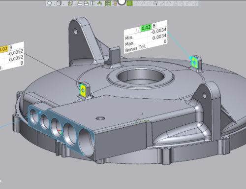
Let’s consider the flat (blue) surface on the water pump cover and ask Control X to check Flatness of the face to .040”.
We see that the Flatness of the face is well within the Flatness tolerance callout. The actual flatness is actually coming out at .0176”.

Since the Flatness callout displays a total tolerance value, we can turn on the +/- values to display the Max and Min values.

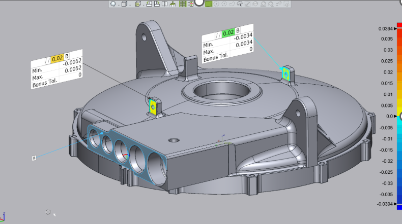
Next, to really examine our surface of interest, we turn on the Fitting Deviation, color mapping tool and can get a much better sense as to exactly what is happening to the face during the face milling operation.
Understanding the color map can be extremely helpful for optimizing your toolpath.
Below, we notice that the center areas of the pump cover are slightly under nominal as indicated by the blue color whereas a few of the external areas of the same flat face are yellow, and slightly full from nominal, indicating that the surface is slightly ‘dished’.
Reviewing such detail regarding machined surfaces can help us achieve better CNC programming practices and produce better parts. Perhaps the face mill is getting pulled into the part as it crosses over the center. Or maybe the fixturing is causing the surface to ‘spring’ after machining.
Understanding where the machined part is deviating from nominal can provide insight as to what is wrong and what can be changed to try to remedy the problem.

Well, this concludes this month’s Metrology Minute. Please contact Joel Pollet with any questions. Joel.pollet@cimquest-inc.com.


Leave A Comment