In today’s blog post we will take a look at a new utility added to Mastercam 2021 called Check Tool Reach.
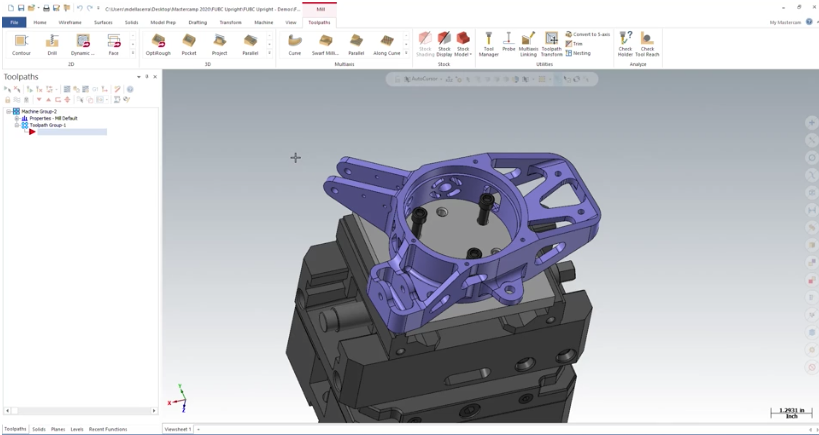
Check Tool Reach can be accessed through the toolpaths menu after a machine is loaded into the file. This utility is used to scan a part model and see if the selected tool has the ability to reach all the features you would want to machine. Using this utility, you can create STL geometry of the result of the scan.
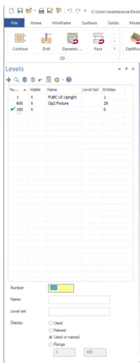
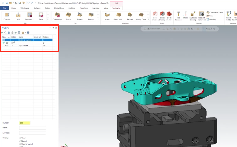
Let’s explore how this works. To begin, you should create a level to save your results to.
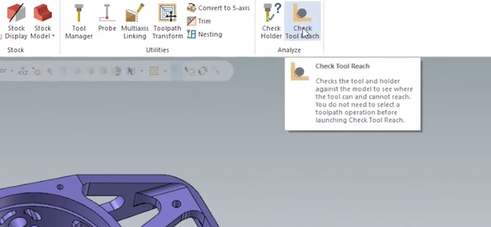
Then you can launch the utility form the toolpaths tab, by selecting Check Tool Reach.
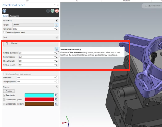
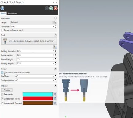
Once you select a target body to scan, you can manually define a tool, or a better option would be to select a tool assembly from your tool library.
In this example, we selected a ¼” tool used for finishing. Since this was a predefined assembly we checked against the defined holder.
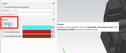
Clicking on the Preview button will display the results of the scan.
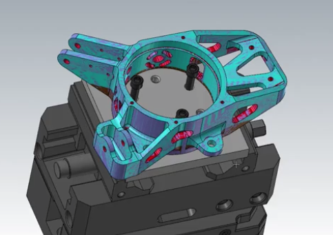
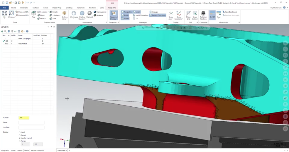
In this case, all reachable areas are shown in the teal blue and areas that cannot be reached by the tool definition will be shown in red. Areas that cannot be reached due to the holder and the assembly information will be shown in brown.
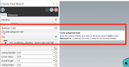
If you wish to save the results, check the Create Polygonal Mesh box.
When you hit the green check to complete the operation your mesh will be created and saved to the level we created earlier. Saving the results will allow you to review them and compare to other scans you may create.
This utility gives you the chance to see if the tooling you have selected can do all the work you need it to, or if a change in tooling is needed.
Please be sure to sign up for our 2 Minute Tuesday video series to receive tips and tricks like this one in video form every week. More info at the button below.




Leave A Comment