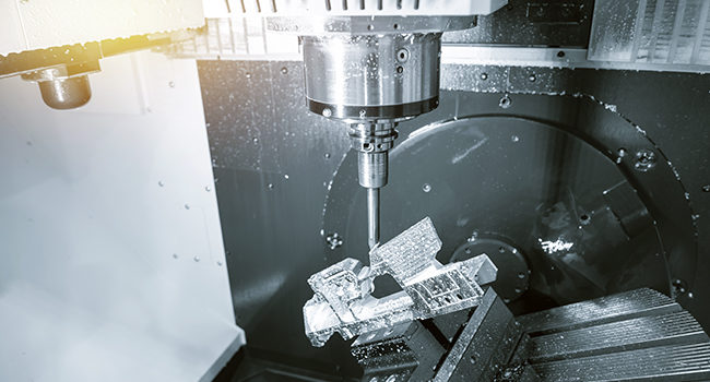
Five-axis machining is taking the machining world by storm, and for good reason. This type of manufacturing, in which computer numerical control is used to move cutting parts or tools along five different axes simultaneously, unlocks incredible potential for any shop. Five-axis machining reduces labor hours, eliminates extra setups, increases production efficiency, and results in beautiful, complex parts. Understanding 5-axis machining is less simple, though. To help, we are breaking down each of the five axes below.
What are the three basic axes?
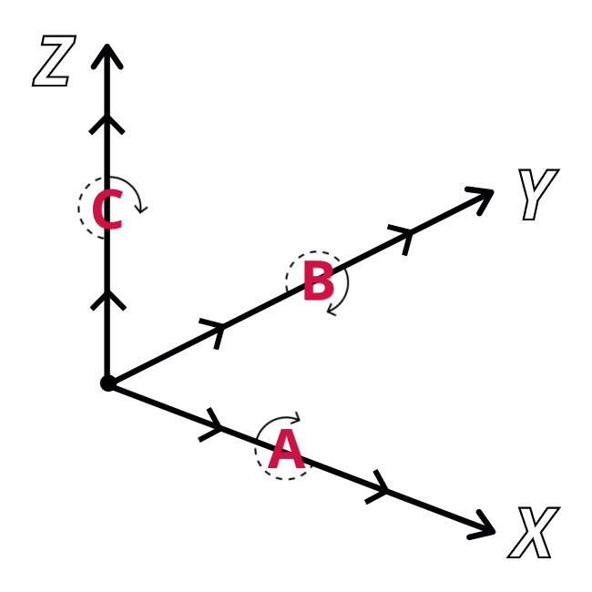
Standard 3-axis milling takes place on the X-, Y-, and Z-axes. These three linear axes are the directions the spindle or part—depending on the machine—can move:
- X-axis: Left-to-right
- Y-axis: Forward-to-back
- Z-axis: Up-and-down
Using all three axes at once, a machine can shave down material to create various three-dimensional objects. It is most useful in situations where the part does not require advanced work-holding, does not have deep or narrow cavities, and can be machined with one setup. For more complex parts, 5-axis machining is better.
What are the “extra” axes on a 5-axis machine?
In addition to the traditional three axes, 5-axis machining also uses two rotary axes: A-, B-, and/or C-.
- A-axis: Rotation around the X-axis
- B-axis: Rotation around the Y-axis
- C-axis: Rotation around the Z-axis
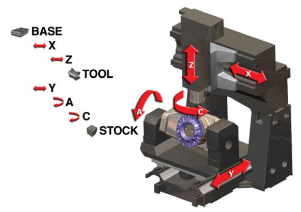
Using rotary axes means that a machine can move either the part or the cutting tool (spindle head) around one of the previously established linear axes. Different machines will use different combinations of axes (A and B, B and C, or A and C), and each configuration suits a different kind of machining.
What are the different multiaxis milling machine configurations?
While there is no “standard” multiaxis milling machine configuration, any 5-axis milling center can be placed into one of the three major machine types: Table/Table, Head/Table, or Head/Head.
Table/Table configuration: This configuration is the most common for multiaxis milling machines. Table/Table machines have two tables that perform all of the rotary work. The first table carries the second table, and the workpiece is affixed to the second table. This means that the tables are the components that spin around the X-,Y-, or Z-axes in A-, B-, or C-. In other words, the part is physically rotated around the cutting tool.
Head/Head configuration: As opposed to having the workpiece rotate around the cutting tool, Head/Head machines use their spindle heads to perform all rotary and pivoting motions. The workpiece itself remains stationary.
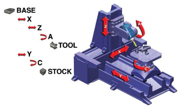
Head/Table configuration: Machines with a Head/Table configuration are a sort of mix between Table/Table and Head/Head. These types of machines have both a rotary table that spins and a tilting head. Some rotary motions are executed by the table, which holds the workpiece, while the spindle head articulates the tool’s tilting motions.
For more information on Mastercam Mill and Multiaxis products, please click the button below.


Leave A Comment