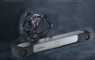
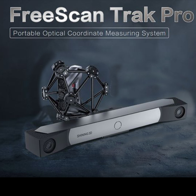
Introducing Freescan Trak Pro 2 – Metrology-grade Scanning of Large Objects
The Freescan Trak Pro2 is a portable optical coordinate measuring system, designed to scan and measure large objects, reaching an accuracy of 23 microns. Reliability of accuracy is achieved through acceptance testing conformance to the VDI/VDE 2634 Part 3 Standard. This testing was conducted in an ISO 17025 accredited Laboratory, assuring users of fast, reliable, and accurate part scans. With two (2), five MP, industrial-grade cameras using 25 crosses (50 blue laser lines) enabling extremely high-speed scanning (just over 3 million points/second) for a smooth scanning experience of very large objects, a car scan like the one below may be captured in just minutes, using just a handful of target markers for the Laser Tracker to monitor. Somewhat similar to the Freescan UE Pro, there are three (3) laser line mode options: 50 Crossing laser lines for high-speed ‘standard’ scanning 7 Parallel laser lines used for combining hi-res scanning with lower res. Single laser line scanning utilizing just one camera and a single laser line for accessing ‘deep’ or somewhat hidden regions where it is difficult for both cameras to ‘see’. As mentioned, large-field scanning using the Trak Pro2 is accomplished using very few targets and a Laser Tracker. Either the Tracker or [...]

Programming your CMM from Mastercam with Verisurf’s Universal CMM
Most modern-day CMM’s will ship with onboard CMM programming software that is powerful yet challenging to learn and use. Companies end up investing weeks and even months getting one or two users proficient with the software. But those individuals can get sick or take vacation at inopportune times or perhaps leave the company. What happens then? Is there a simple way to transition a Mastercam CNC Programmer into a CMM programmer? Verisurf’s Universal CMM (UCMM) enables a CMM programmer to develop inspection plans utilizing all of the same graphical tools used when CNC programming a part in Mastercam. The Verisurf User Interface ‘is’ the Mastercam User Interface and includes the Verisurf tools for creation and execution of inspection plans. The UCMM supports virtually all common CMM brands and models. Advanced GD&T evaluations and reporting are also included. Also supported are probe-changers, head indexers, probe ‘scanning’ and all joystick functionality. So users will not sacrifice power or capabilities by switching to the UCMM. Perhaps the most important attribute of the UCMM is that it doesn’t disable your existing CMM programming software. So, for example, if you have thousands of part inspection plans already created in your existing CMM programming software, those will all still [...]

UltiMaker Launches New Factor 4 3D Printer
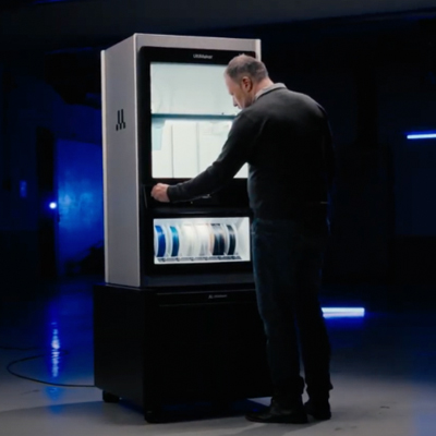
UltiMaker Launches Factor 4, a New Standard in Industrial-Grade 3D Printing UltiMaker recently announced the release of the UltiMaker Factor 4 industrial-grade 3D printer, designed to take manufacturing to new levels of efficiency and reliability. Factor 4 is an end-to-end 3D printing solution for light industrial applications. The UltiMaker Factor 4 3D printer is engineered for the development and production of process-critical tools and components. With support for engineering materials, direct drive dual extrusion, onboard print quality reporting, temperature-controlled build volume, and other innovative features, it delivers high levels of predictability and minimal variance. Built on over a decade of dedication to openness and accessibility, the machine will support one of the widest material portfolios on the market for a variety of applications, including end-use parts, functional prototyping, manufacturing tools, and small batch manufacturing of auxiliary components and spares. Factor 4 offers a temperature-controlled build volume of 330 x 240 x 300 mm and uniform bed heating, ensuring consistent performance across the entire build plate. Designed for manufacturing and industrial sectors, it launches with a new high-temperature print core that allows engineers to print up to 340°C, enabling a broader range of high-performance, temperature-resistant, and durable materials, such as the new UltiMaker PPS [...]
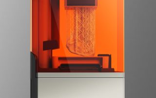
Introducing the New Formlabs’ New Form 4
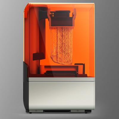
Formlabs recently announced the new Form 4, their next-generation resin 3D printer that redefines the industry standard for speed, accuracy, reliability, and material versatility. Form 4 and its biocompatible version, Form 4B, represents the next evolution in stereolithography (SLA) 3D printing technology, built upon years of groundbreaking hardware, software, and materials science innovations. With unprecedented speed, Form 4/B delivers the majority of parts in under two hours, in all materials, without ever compromising on dimensional accuracy or surface finish. Form 4 combines a new print engine with updates to the Formlabs materials library — 23 unique resins on Form 4 and 37 on Form 4B available at launch — as well as new accessories and post-processing solutions, and an improved user experience. These updates reaffirm that Formlabs’ resin 3D printing ecosystem is the most powerful tool available for any professional to turn their ideas into reality. Please click below to learn more about this new 3D printer. More Details
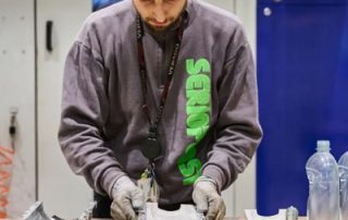
Formlabs 3D Printing Boosts the Fast-Mosting Consumer Goods Industry
Fast-Moving Consumer Goods (FMCG) provider Unilever and Serioplast Global Services are leveraging Formlabs’ 3D printing technology to overhaul the conventional process of developing and testing new bottle designs. As per Formlabs, the journey from conceptualizing a design to mass-producing plastic bottles has been arduous and costly. The conventional method primarily involves blow molding, requiring intricate metal tooling and specialized equipment. This process is characterized by prolonged production cycles and substantial expenses, posing challenges for companies in the FMCG sector. With room for improvement in packaging development, Unilever and Serioplast partnered to explore the feasibility of using 3D-printed molds for low-volume stretch blow molding (SBM). This approach aimed to streamline prototyping and pilot testing processes, reducing lead time by six weeks and costs by up to 90%. “A consumer goods company like Unilever must be on the market as soon as possible or before your competitors. You need to offer the best product at the best price in the shortest time possible to the consumers. 3D printing helps us speed up this process,” said, Stefano Cademartiri, CAD & Prototyping Owner, Unilever. The mold 3D printed with Rigid 10K Resin is manually polished and then assembled into a metal frame. Photo via Formlabs. [...]
Kimya’s ABS-ESD Filament
Kimya's ABS-ESD Filament Join us to learn about the 3D filament Kimya ABS-ESD, thanks to which those in the industry can produce and use ESD-safe parts providing secure operations in explosive zones, cleanroom environments, and manufacturing plants of sensitive industrial devices.