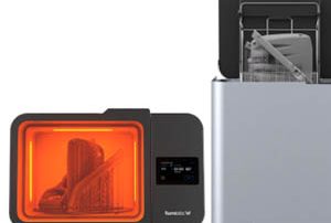
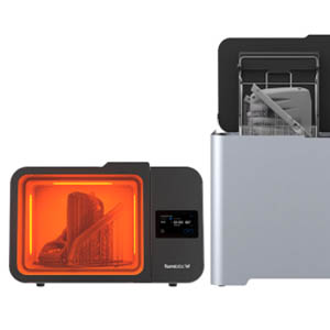
Form 3L and Form 3BL: A Complete Ecosystem for Large Part Production
Form 3L and Form 3BL: A Complete Ecosystem for Large Part Production, Now With Automated Post-Processing Take control of large-scale part production, increase your throughput, and bring your biggest ideas to life with the Form 3L and Form 3BL, cost-effective large-format SLA 3D printers. With the recent launch of Formlabs’s automated large-format post-processing machines, Form Wash L and Form Cure L, the Form 3L and Form 3BL ecosystems now streamline the 3D printing workflow to produce ready-to-use parts with minimal intervention. Form Wash L automates the removal of residual resin after printing while Form Cure L completes the curing process to help parts achieve peak mechanical properties and dimensional accuracy. Alongside our wide range of materials, the Form 3L ecosystem is the ideal 3D printing solution for cost-effective, in-house, large-scale production. Pre-order the Formlabs Form Wash L & Form Cure L before December 17th, 2021 and receive a $200 discount. Request a Quote

ABS 3D Printing – Easy as PLA with MakerBot RapidRinse
ABS is one of the most popular manufacturing polymers in the world, but desktop 3D printing with ABS has always been challenging. Warped and failed prints, expensive wash tanks, and chemicals for dissolving support material have all been limiting factors. Now you can print and post-process ABS parts as easily, and consistently as PLA with the new MakerBot RapidRinse™ Fast-Dissolving Support Material. Be one of the first 100 to join the ABS revolution with MakerBot RapidRinse and get a FREE RapidRinse Super bundle when you purchase your METHOD X 3D printer: 6 spools ABS-R + 3 spools RapidRinse Fast Dissolving support material. Request a Quote

Metrology Minute – Geometry Deviation
Geometry Deviation is a tool for measuring essentially everything that might be relevant for size, orientation, and location for a specific feature. For example, when measuring geometry deviation for a cylinder, the criteria of interest would likely be the size, location, and centerline axis direction as they all compare to the nominal (exact) CAD model. As you review the data blocks below, Control X can compare the scan data values to the CAD data values and show the results in clear, unambiguous text blocks. “Paired” information is the data relative to the scan as it compares to the CAD model. The values are based upon the current coordinate system. To dig deeper into the ‘Form’ of any cylindrical feature on your part, Cylindricity may also be analyzed using Control X in order to check the general Roundness of a cylinder across the complete length of the feature. Min and max values for the Cylindricity test are shown below. Notice datum information isn’t required to test Cylindricity. As you may recall from last month’s Metrology Minute, Fitting Deviation Maps may also be turned on for each cylinder to dig deeper into exactly where Cylindricity may be off. In reviewing the isolated deviation color map, [...]

Manufacturing Soup
Additive design, 3D printing, Traditional CAD, Traditional CAM, Hybrid Machining, 3D Scanning, Scan Processing, Reverse Engineering, Inspection . . . Each discipline is evolving exponentially on its own, but each also crosses over into neighboring technologies, all contributing to the rapidly evolving world we refer to as “Manufacturing”. In studying the sciences, one can quickly come to the conclusion that all disciplines are subsets of Physics. When Biology, Math, and Chemistry students advance to high-level courses they realize how the sciences are interwoven, dependent on each other and all are powerful contributors to the study of Physics. In our world, it’s all about “Manufacturing”. Products like Mastercam, offering a “Subtractive Manufacturing” process, continues to improve its toolpathing capabilities in areas such as multi-axis machining, adaption of new cutting technologies, new toolpath styles, and evolving machinery capabilities for faster throughput, better efficiency and expanded tool life. 3D Printing, offering an “Additive Manufacturing” process, continues to grow in material options, printing efficiency, speed and reduction of cost. But consider how 3D Printers have limitations such as; part sizes, post-processing options, part accuracy, surface finish and supported materials. Remarkably similar parameters to consider when selecting new CNC machinery for Subtractive applications. Scanning and Scan Processing was [...]

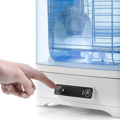
Ultimaker Recently Announced PVA Removal Station
a reprint from https://www.fabbaloo.com/news/ultimaker-announces-pva-removal-station Ultimaker CTO Miguel Calvo introduces the new PVA Removal Station [Source: Ultimaker] In an unusual online announcement, Ultimaker revealed an upcoming cleaning station. The company now bills itself as the “number one maker of professional 3D printers”, and they’re likely correct on that count. They’ve fully transformed from the hobbyist background from their launch, some ten years ago. Now the company markets equipment for professionals in various industries and corporate environments. Their strategies to get there have been quite effective. For example, one strategy they used in the past was to offer equipment that automatically “found” each other on a company’s internal network to set up a 3D print workgroup. While that might seem like a simple technical feature, in practical terms it allowed a department to buy a workgroup of 3D printers without having to involve the IT department. For those in corporate environments, you know what that usually means. Turning on the new PVA Removal Station [Source: Ultimaker] It’s this style of detailed approach that seems to have been Ultimaker’s key to success. They carefully look at their clients and attempt to overcome their challenges. In the past year, they’ve tried to solve the [...]
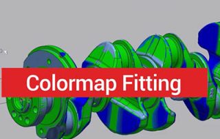
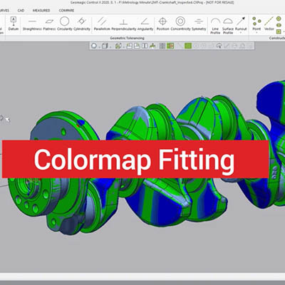
Color Map Fitting Inside Control X
In this blog post, we are going to take a look at Color Map Fitting inside of Control X. Color Map Fitting is a useful tool for analyzing the tolerances of 3D scan mesh files, relative to the original model. The image above shows a CAD model of a crankshaft with the scan mesh superimposed on the model. The image below shows the Color Map Fitting. We first selected the flatness of the scanned mesh face. By turning on the checkbox for fitting deviation, the software will show how the scan data truly fits to the CAD model. Turning off the CAD model will give a better visual through the color map. In this example, we are setting to check for a flatness of 2 millimeters. What this means is that the worst-case scenarios for flatness are points that are plus or minus 0.4 millimeters. This means we should be well within tolerance. The colors indicate where the face is high and where it’s low. The resolution of the scanner comes into play and generally the edges are going to be where you see the majority of the deviation. Next, we can check parallelism to make sure that it’s within 5 millimeters. On [...]