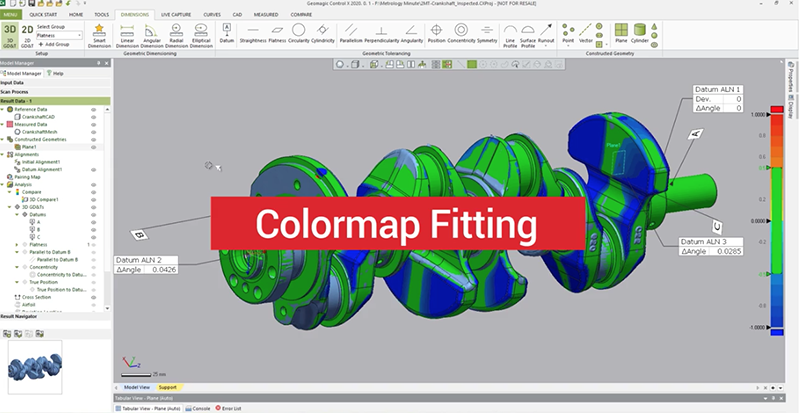
In this blog post, we are going to take a look at Color Map Fitting inside of Control X. Color Map Fitting is a useful tool for analyzing the tolerances of 3D scan mesh files, relative to the original model.
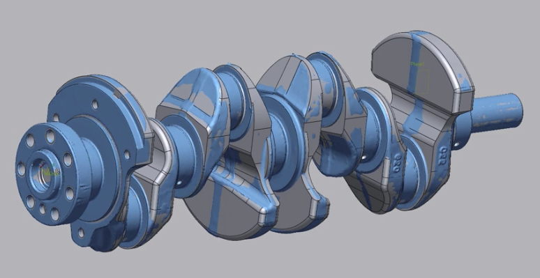
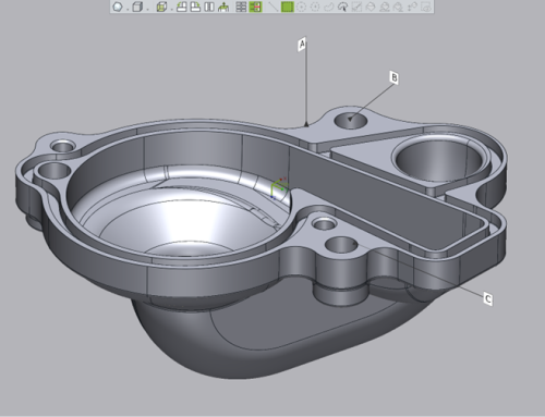
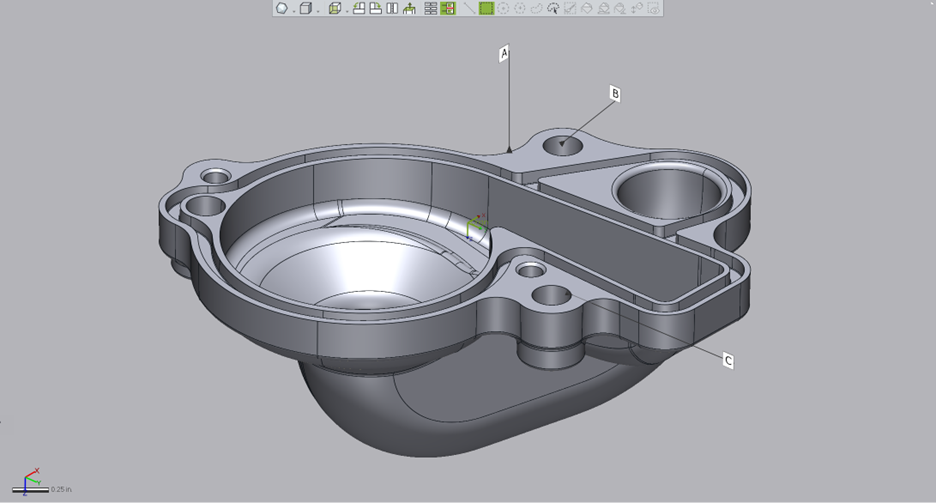
The image above shows a CAD model of a crankshaft with the scan mesh superimposed on the model. The image below shows the Color Map Fitting.
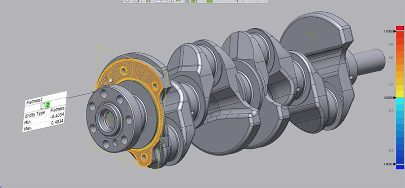
We first selected the flatness of the scanned mesh face. By turning on the checkbox for fitting deviation, the software will show how the scan data truly fits to the CAD model. Turning off the CAD model will give a better visual through the color map.
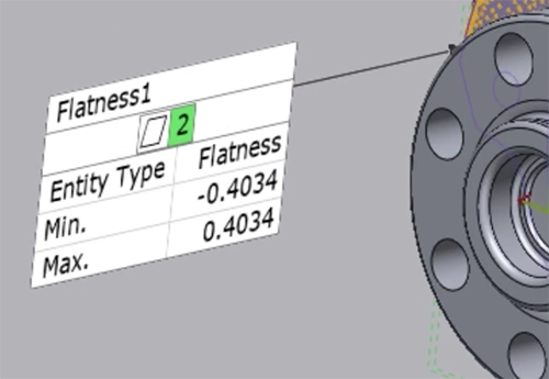
In this example, we are setting to check for a flatness of 2 millimeters. What this means is that the worst-case scenarios for flatness are points that are plus or minus 0.4 millimeters. This means we should be well within tolerance.
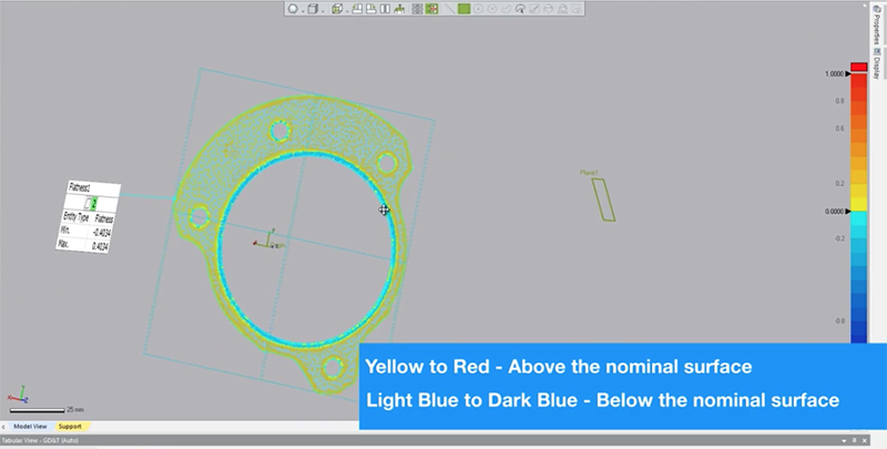
The colors indicate where the face is high and where it’s low. The resolution of the scanner comes into play and generally the edges are going to be where you see the majority of the deviation.
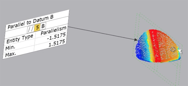
Next, we can check parallelism to make sure that it’s within 5 millimeters. On the color map shown above you will see that it’s trending from yellow to red and then back to yellow into blue. This face is bowing. It’s curving out where it’s becoming more full and then it actually goes to being a little bit undersized indicating that it is actually a bowed image.
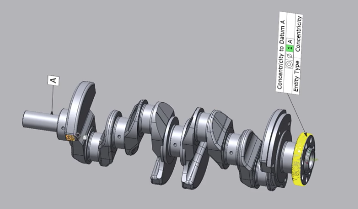
Next, we will check the concentricity of this cylinder relative to datum A. From a concentricity standpoint of one millimeter, this is within high tolerance of the part.
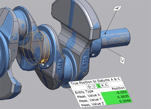
Now we can check for the true position. This is to check for the true position of the drilled hole relative to datums A and C. For holes, the color map isn’t as telling, since the only areas picked up in scans are at the ends, where the scanner can see. But the true position is really checking for the XYZ of those holes.
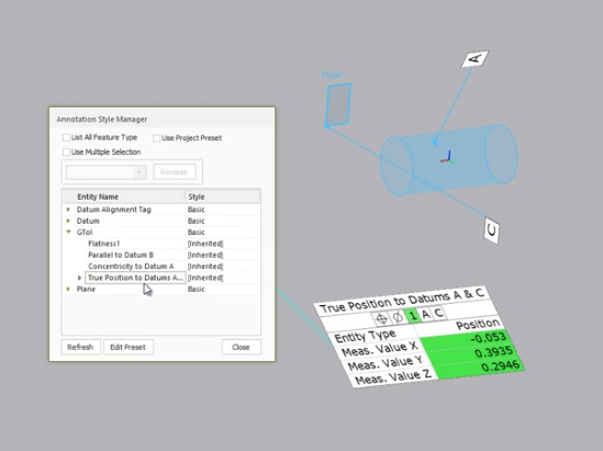
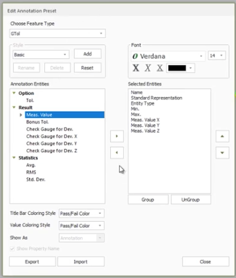
With Control X, you can double-click to change your dimensions or you can right-click to edit presets for the true position. You can also add other information such as the measurement value which is the overall measured deviation or the average.
Color Map Fitting provides a clear visual of your scanned mesh tolerances in relation to the original CAD model. Please click the button before for more information on Control X.


Leave A Comment