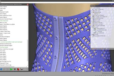
Introducing Geomagic Freeform and Freeform Plus
Cimquest is proud to announce the addition of the Geomagic Freeform and Freeform Plus organic modeling software products to our powerful line of Geomagic technology. Geomagic Freeform and Freeform Plus are commonly used in the medical industry for the design and development of appliances used during medical and surgical procedures and many users are virtually modeling very detailed artwork. Freeform can start with a blank screen and completely design an incredibly complex appliance or piece of art from scratch. It can also work from existing CAD data as well as from existing scan or CT scans which may be used to aid in the design development. The Geomagic comprehensive StructureFX toolset gives you the freedom to select existing patterns or create complex internal and external lattice structures from scratch for incredible designs. Advanced modeling tools may be used to create functional cages for applications such as custom medical implants. Below is a spine cage that was designed in Freeform Plus utilizing CT scan data. Incorporating the Touch or Touch X haptic devices presents the ultimate in expressive freedom and fast model design. Freeform and Freeform Plus work exclusively with the Touch and Touch X Haptic devices to deliver freedom of motion through the [...]
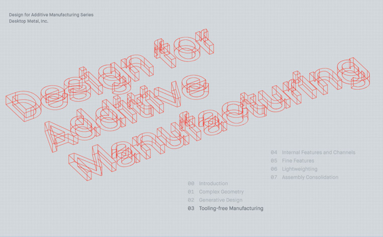
Tooling-free Manufacturing with Desktop Metal
Without the need to manufacture jigs, fixtures, or molds, engineers and designers can go from design to functional part in as little as a day. If needed, designers can print multiple versions of a part, then quickly iterate on the design based on functional testing results. The speed and accessibility of additive manufacturing allows design teams to go through dozens of design iterations in as little as a week. Once part designs are finalized, binder jetting technology makes it easy to go from printing one-off, low-volume prototypes to producing thousands or even up to millions of parts. Because there is no need for tooling or complex set-ups, manufacturers can produce a part one day, and switch to a new part the next, with no delay in production. Tooling-free Manufacturing Additive technology also enables DfAM principles by eliminating the need for hard tooling. Without the need to manufacture jigs, fixtures or molds, engineers and designers can go from design to functional part in as little as a day. If needed, designers can print multiple versions of a part, then quickly iterate on the design based on functional testing results. The speed and accessibility of additive manufacturing allows design teams to go through dozens of [...]

Laser Powder Bed Metal printing with Xact Metal – Webinar on Demand
Laser Powder Bed Metal printing with Xact Metal Learn about Xact Metal's mission to produce an entry-level LPBF printer (Laser Powder-bed Fusion) to be accessible to more companies, but without sacrificing accuracy, resolution, and high cost of start-up. https://cimquesttv.wistia.com/medias/71mwhlwdod?embedType=async&videoFoam=true&videoWidth=640

Exploring the MakerBot Method 3D Printer
Let's take a look at the Makerbot Method Series. A performance platform, the Method bridges the gap between industrial 3D printing accuracy and desktop accessibility. The Method Series offers an entry into industrial applications at an affordable price. Built on the bedrock of proven FDM technology from Stratasys, the Method series leverages 21 industrial patents. This distinguishes Method from many of the other entry-level 3D printers on the market. Let's take a look at some of the key features. It all starts with the patented circulating heating chamber. The circulating heated chamber utilizes two heat exchangers with active blowers to fully envelop each print with hot air during the entire print. The result is consistent dimensional accuracy within .2mm and optimal part strength. Method is a dual extrusion platform with thermal cores 50% longer than most desktops, allowing for more control and faster print speeds. Inside, the rigid full-body metal frame eliminates flexing that typically occurs during high-speed print movement. Less flexing means more consistent prints with better part accuracy. The flexible spring steel build plate sits on a factory-calibrated base, machined from aluminum. The plate leverages high-strength magnets for easy print removal. Once a part is complete, the plate comes off of [...]
Keep it Real – Four Applications to Increase Productivity
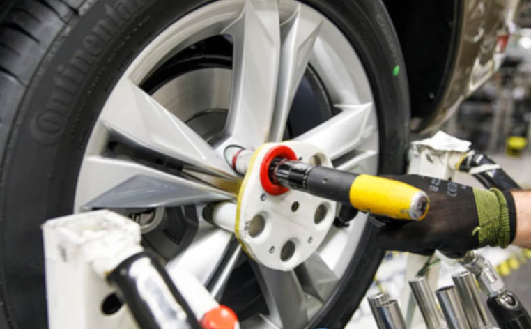
Working more efficiently and effectively is a goal of essentially every organization, regardless of sector or industry. Using 3D printing, many companies around the world can increase productivity in warehouses, assembly lines, and factories, enabling them to achieve results otherwise impossible. Read on for real-world applications that companies are leveraging to increase their productivity. Support Tools and Quick Fixes In a fast-moving environment, time matters. Take Heineken’s bottling plant in Seville, Spain, for instance, which produces more than 500 million liters of beer each year. Efficiency is the name of the game, which means spare parts and other tools must be quickly available should the need arise. Using 3D printing, Heineken is able to print spare parts and tools on demand, minimizing downtime and ensuring that product is continuously manufactured. Trivium, which manufactures tin packaging for products used in industries such as beauty and personal care, food and beverage, and pharmaceutical, uses a device that measures the speed of its conveyor belts. When the wheel of this device broke, however, the company was often left waiting on a replacement. By 3D printing the wheel, downtime was reduced from days – or even weeks – to hours. Assembly Tools Workers at both Ford's Cologne and [...]

Cimquest Used Demo Equipment Annual Sale
We are selling a few of our demo 3D printers. If you are in the market for a 3D printer and are looking for a good deal, please see below for the machines currently available. Fortus 900mc Gen2 (Stratasys) - $229,000 (OBO) FDM Technology 36” x 24” x 36” Build Envelope Capable of running these materials. HP Jet Fusion 5200 (20% Discount) Multijet Fusion Technology (MJF) 15” x 11.2” x15” Build Envelope Supports: PA11, PA12, PA12 Glass Bead, TPU, PP Optional Upgrade to the 5210 Desktop Metal Studio (20% Discount) Bound Metal Deposition Supports: 17-4, 316L, H13, 4140, Copper Optional Upgrade to the Studio 2 xRize Printer ($19,000) 12” x 12” x 8” Build Envelope FFF with Full Color Printing Supports: Rizium One, Rizium Carbon, Rizium ST - for full color 3D Rize One Printer ($5,000) 12” x 12” x 6” Build Envelope FFF with Blue Scale Markin Supports: Rizium One & Rizium Carbon Please contact us for more information. Contact Us