Tech Tips

2 11, 2016

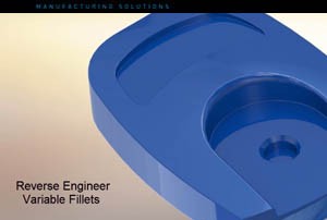
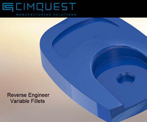
Reverse Engineering Variable Fillets

By |2016-12-15T14:30:55-05:00November 2nd, 2016|Categories: 3D Scanning, Tech Tips|0 Comments

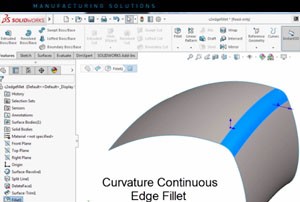
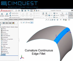
Let’s explore how to reverse engineer a variable fillet from a polygonal mesh . . . When reverse engineering a physical model, radius values can be measured with various types of radius gauges. It can be somewhat of a challenge if the fillet face is worn, chipped, or distorted. In addition, the task becomes more complex if the fillet is not constant, that is, if it varies along the edge like the mouse shown below. [...]

26 08, 2016

SolidWorks 2016 – Replacing Sub-assemblies with Multi-body Parts

By |2016-12-15T14:30:56-05:00August 26th, 2016|Categories: SOLIDWORKS, Tech Tips|0 Comments

Today we will explain how to replace subassemblies with multibody parts, a new function in SolidWorks 2016. Unlike previous versions of SolidWorks, in 2016 you can use a multibody part as a simplified representation of the assembly. When you make changes to the subassembly and save an updated multibody part, this version can replace the older copy without having to recreate the mates. Consider the assembly shown above. It contains two individual parts and two [...]

3 08, 2016

Working With SOLIDWORKS 2016 Edge Flanges

By |2016-12-15T14:30:57-05:00August 3rd, 2016|Categories: SOLIDWORKS, Tech Tips|0 Comments

In today's episode of “What’s New in SolidWorks 2016” I’m going to show you an enhancement to sheet metal flanges that will allow you to create edge flanges that are longer than the edge to which they are attached. In previous versions of SolidWorks, an edge flange feature would default to the length of the edge of the sheet metal part with no options to manipulate the flange length. This is no longer the case. [...]

18 07, 2016

Creating Rods and Tubes in SolidWorks 2016

By |2016-12-15T14:30:58-05:00July 18th, 2016|Categories: SOLIDWORKS, Tech Tips|0 Comments

SolidWorks 2016 includes an enhancement to sweeping solids, cuts, and surfaces that will allow you to create a solid rod or hollow tub along a sketch line, edge or curve directly on a model without having to create a new sketch. This is possible with the new “circular profile” option in sweeping operations. The example part above has several edges that can be used as sweep paths. In order to cut a tube through the [...]

8 06, 2016

SolidWorks 2016 Bidirectional Sweep

By |2016-12-15T14:30:59-05:00June 8th, 2016|Categories: SOLIDWORKS, Tech Tips|0 Comments

There’s a new enhancement to the sweep function in SolidWorks 2016 that will allow you to create sweeps for a mid-path profile in either direction or bidirectional. In previous versions of SolidWorks, a profile had to sweep the entire length of the path, no matter the location of the profile sketch. This is no longer the case. Now mid-path profiles can be swept using direction 1, direction 2, or both directions. This simple part (below) [...]

11 05, 2016

Curvature Continuous Edge Fillet – SolidWorks 2016

By |2016-12-15T14:30:59-05:00May 11th, 2016|Categories: SOLIDWORKS, Tech Tips|0 Comments

There is a new enhancement in SolidWorks 2016 that will allow you to define the edges of constant and variable fillets as curvature continuous. This option creates a smoother curvature between adjacent surfaces. Here’s an example of how it works . . . The part shown above contains two surfaces that meet at a sharp edge. Select the edge, and go to Insert > Features > and select Fillet/Round. In the property manager under Fillet [...]

18 04, 2016

SOLIDWORKS 2016 Mate Positions

By |2016-12-15T14:31:00-05:00April 18th, 2016|Categories: SOLIDWORKS, Tech Tips|0 Comments

SolidWorks 2016 includes an enhancement for creating and editing mates that will allow you to manipulate specific mates such as: angle, distance, Limit Angle, Limit Distance, Slot, and Width mates all in one convenient table called the Mate Controller. In Mate Controller, you can show and save the positions of assembly components at various mate values and degrees of freedom without using configurations for each position. You can also create animations based on the positions [...]

26 01, 2016

SolidWorks 2016 – Selection Breadcrumb

By |2016-12-15T14:31:02-05:00January 26th, 2016|Categories: Tech Tips|0 Comments

There is a new feature in the design interface of SolidWorks 2016 called “Selection Breadcrumbs” that will allow you to select a part or feature in the graphics area and then refine that selection through the context-based representation of the item, or the “trail of breadcrumbs” connected to the selection. Take this assembly made up of 4 mated parts. When you select a face, you can see all of the mates of the component that [...]

Go to Top