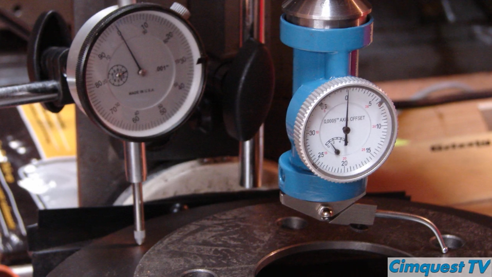
There are various types of dial indicators and other manual gauges that can be used to inspect freeform surfaces and determine if they are within tolerance. However, inspecting surface profile tolerances can be quite challenging when you are measuring freeform surfaces.
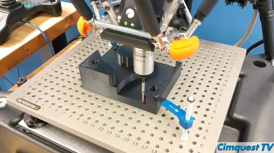
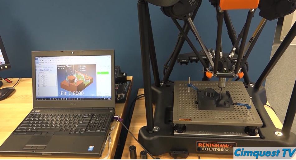
One solution for this scenario is utilizing Verisurf software along with the CMM Master.
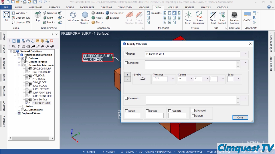
In Verisurf, you can define the Geometric Characteristic, the Tolerance Zone Size, and add the Datum References called out on the manufacturing drawing.
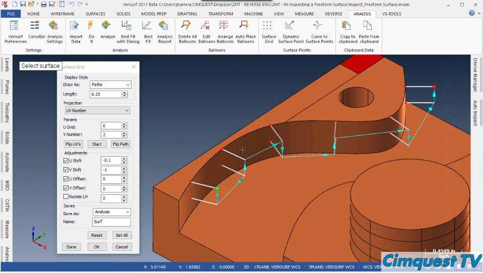
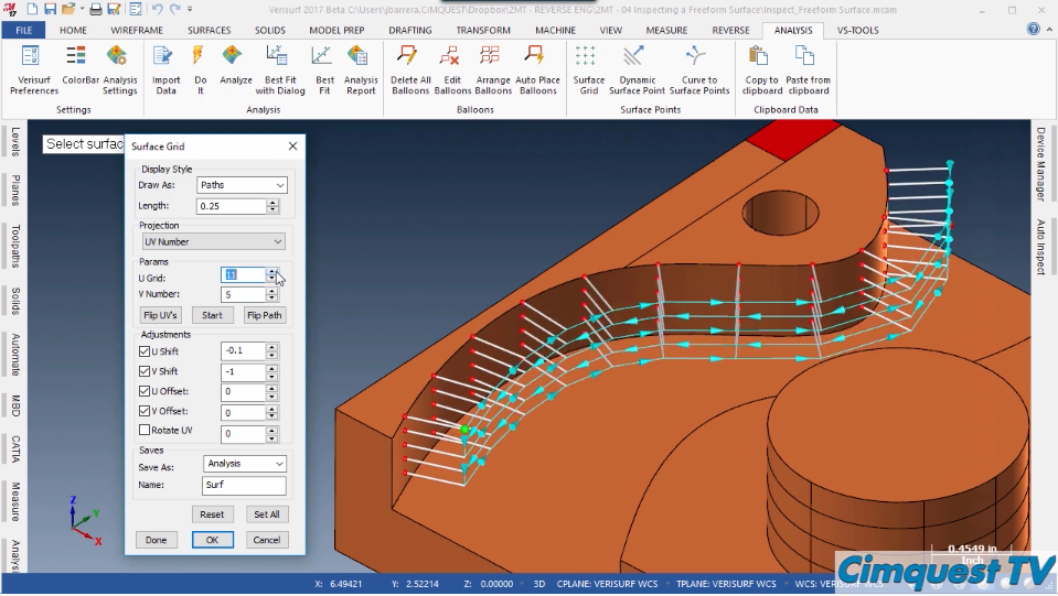
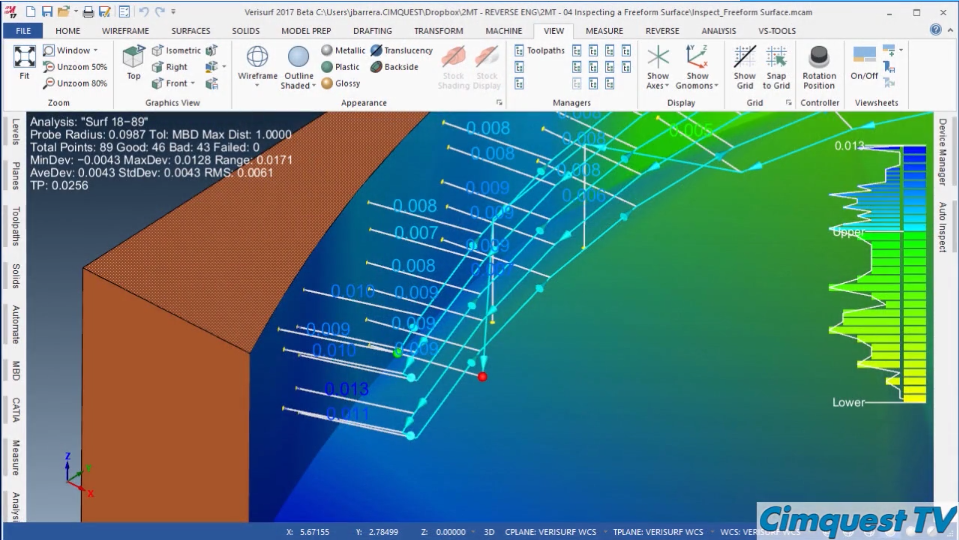
Next, add a surface grid of points on that freeform surface.
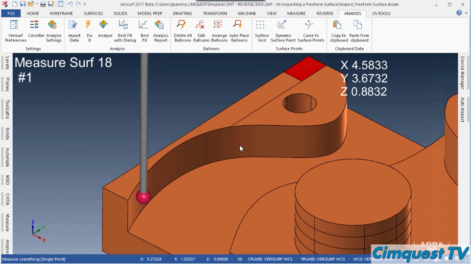
The probe will scan and analyze each one of these points as it sweeps across the surface. You can control the density of the scan points, as well as the path direction the probe will take.
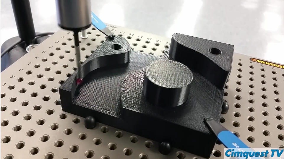
Once you finish programming the probe path, use the CMM Master to inspect it. The probe then follows the automated repeatable path created in the Verisurf software, and quickly scans and collects the data from each grid point.
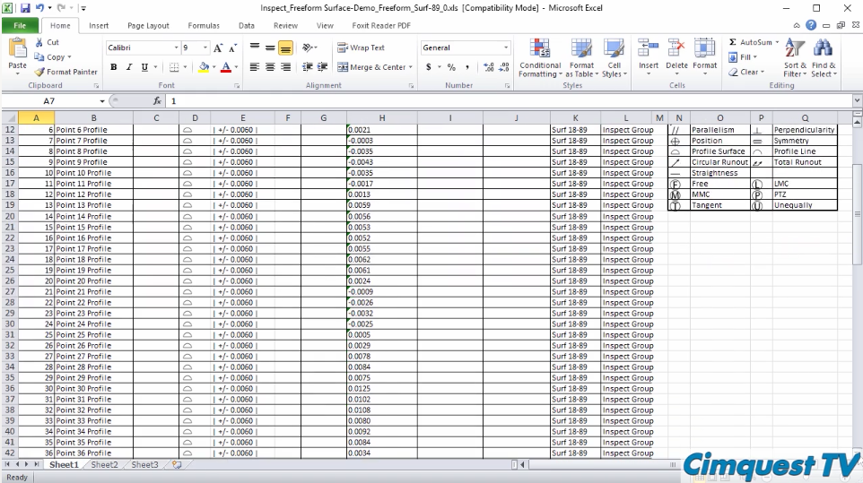
Once this process is done, you can easily produce a First Article Inspection report per AS9102 REV B standard, or output a PDF with the tolerance information.
As you can see, inspecting a freeform 3D surface just got whole lot easier using the Verisurf Automate module, along with the CMM Master.
Please be sure to sign up for our 2 Minute Tuesday video series to receive tips and tricks like this one in video form every week. More info at the button below.
[button link=”https://cimquest-inc.com/2-minute-tuesday/” color=”default” size=”” stretch=”” type=”” shape=”” target=”_self” title=”” gradient_colors=”|” gradient_hover_colors=”|” accent_color=”” accent_hover_color=”” bevel_color=”” border_width=”1px” icon=”” icon_divider=”yes” icon_position=”left” modal=”” animation_type=”0″ animation_direction=”down” animation_speed=”0.1″ animation_offset=”” alignment=”left” class=”” id=””]Sign up[/button]





Leave A Comment