Analyzing airfoil shapes is easier than ever using the Control X Airfoil Analysis technology. Upon completion of scanning the airfoil and aligning with the nominal CAD model, the software is able to return dozens of useful parameters, necessary for complete airfoil analysis. Some of the parameters include:
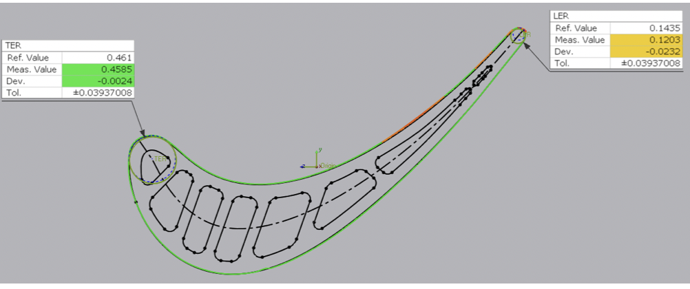
Leading and trailing edge radii
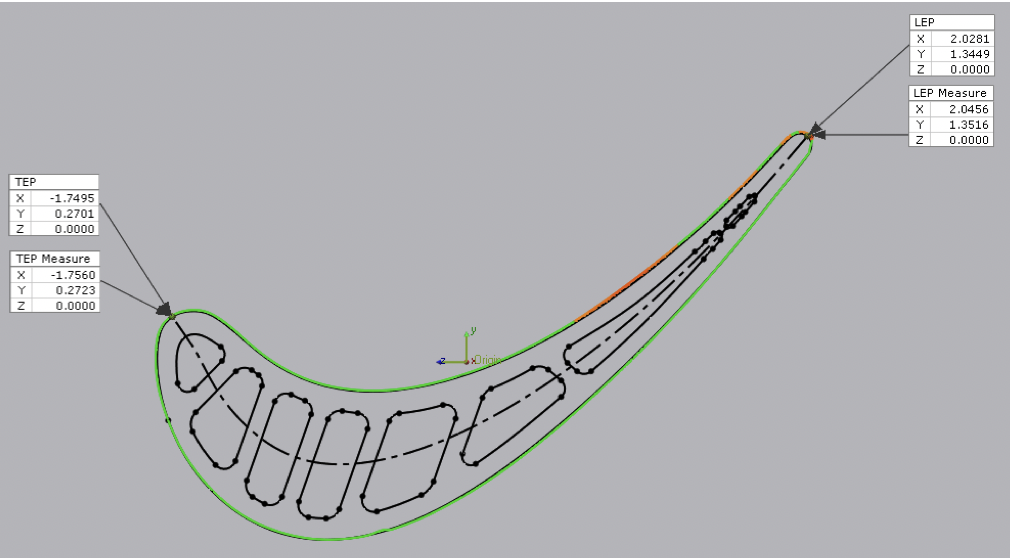
Leading and trailing edge positions in space
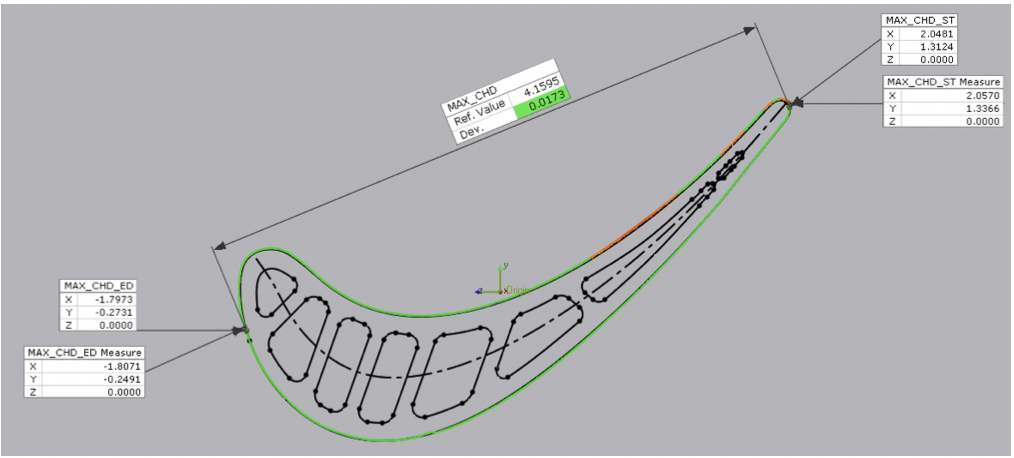
Maximum chord height
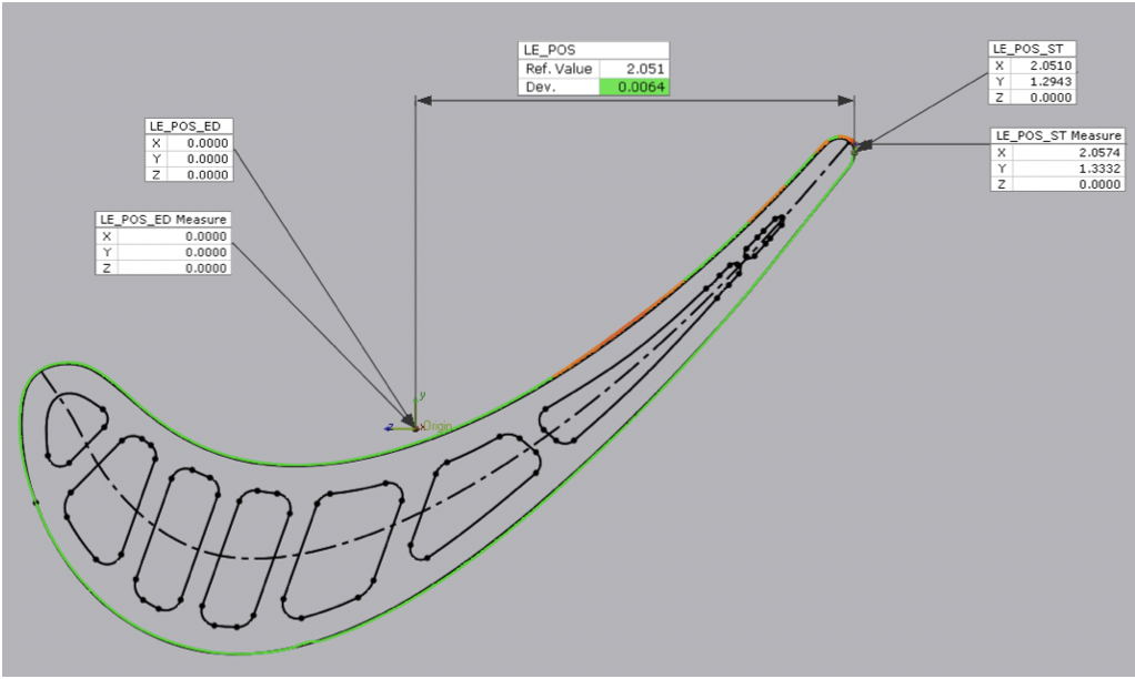
Leading (and trailing) Edge position in space relative to the model origin
Axial chord length
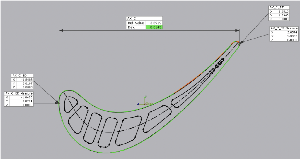
The leading and trailing edge thicknesses, as well as maximum airfoil thickness across the widest section, may be easily requested using this powerful tool making complete airfoil analysis simple with just a few clicks of the mouse.
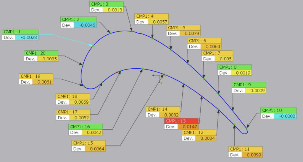
Additionally, analyzing airfoils often requires identifying points along a section’s periphery and comparing those to the corresponding points from the nominal CAD model. Deploying the Comparison Point function in Control X, this too is handled by just a click or two of the mouse.
For any questions or comments, please contact Joel Pollet by clicking below.


Leave A Comment