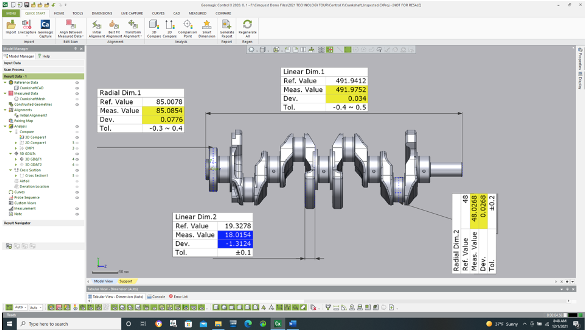
The optimal workflow in Control X for inspection is to compare the scan of a manufactured part to its corresponding nominal CAD model. This is done by first aligning the scan to the CAD model, typically utilizing datums for the alignment. Once the alignment is complete, any type of dimension, whether feature size, distance, GD&T, etc. may be derived by essentially comparing the dimensions of the scan to those of the nominal CAD model. The system can then report the Reference (Ref.) value (or CAD model dimension) as compared to the Measured (Meas.) value (or scan dimension) and display the differences, whether the dimension is within tolerance or not, and by how much.
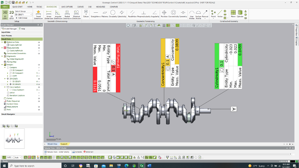
GD&T information can also be obtained fairly quickly by having the CAD model for comparison and, when needed, defined datums. Below, Datum A is used for both a Total Runout and a Concentricity dimension. The Cylindricity callout does not require a Datum to be used in the definition.
So when the CAD model is available, Control X offers an excellent process for metrology by integrating the nominal CAD model into the inspection process. But what about when there is no CAD model? What if just a 2D inspection drawing is available? Then we can do things “the old-fashioned way” but still take advantage of having the manufactured part scan.
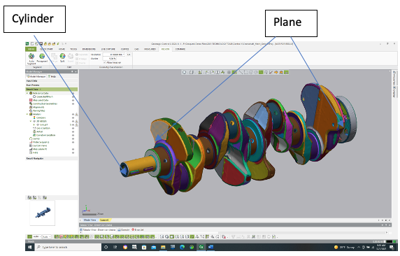
The scan is imported into Control X and Regions are created. A Control X Regions model colors every analytic face with a unique color, signifying the analytic geometric shape the Region represents. If the scan was “perfect” and the scanned part was “perfect” the user would see one color per analytic feature. But certainly manufactured parts are never perfect, so multiple colors signify deviations from the perfect shape. For shapes that cannot be defined using equations, they would be classified as “Freeform”.
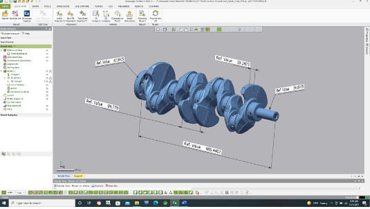
Once the Regions’ Model is prepared by Control X, a user can read dimensions, tolerances, etc. off of a 2D print, then measure those same dimensions using Control X and display them on the Control X screen for inspection. While the depth of data is not available due to the lack of a CAD model, just a scan alone may be used to do a more traditional method of measuring and inspection. We’re just replacing physical measurement tools with the virtual measurement tools of Control X and utilizing the Regions’ model.
Please contact Joel Pollet at Cimquest with any questions or to receive additional information.


Leave A Comment