The Benefit of using GD&T and a Positional Tolerance vs +/- Tolerances
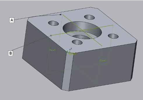
When creating a part like the one below, the intent of the four holes is likely to fasten this component to another in the final assembly where the round holes will accept round fasteners. We want to look for a way to maximize our tolerance to provide as few scrapped parts as possible.
A typical dimensioning scheme using +/- tolerances might look something like this, defining the hole’s locations off of the adjacent flat surfaces.

Furthermore, consider the datums as playing a key role in how the part will fit inside the final assembly. The datums allow the designer to simulate the part in the assembly. Consider datums A and B below.
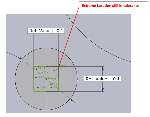
Now consider how the hole’s location tolerance is placed as +/-.050”. This created a tolerance box of .1” x .1”, surrounding the ‘perfect’ hole center.

Therefore, any manufactured holes where the center points fit inside that square will represent an in-spec hole location.
But now, consider any of the four corner points of the box, representing the extreme location that still fit the tolerance conditions.
Our goal in manufacturing is to provide as much acceptable tolerance as possible to keep costs down and manufactured parts within spec up. Remember, we’ll be fitting round fasteners inside of round holes. So why are we dealing with a square tolerance zone?
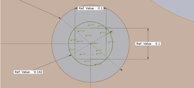
Any points the same distance away from the exact hole center (i.e. the ‘radius’ away) will also meet the manufacturing requirements.
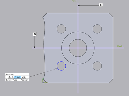
Using simple math, we can calculate the diameter of this ‘tolerance circle’, centered at the perfect hole center location as .142”.
Therefore, any points either lying on or within that .142 diameter circle would also fit the designer’s requirements. But notice it also provides a much larger tolerance zone, roughly 56% larger. Notice the points that are outside of the +/- tolerance box but on or inside the .142 diameter circle. ANY of these points would meet the same design/manufacturing requirements.
Continuing on, earlier we discussed the benefit of tying datums into the dimensioning scheme. As a reminder, datum locations are ‘perfect’ and represent exactly how our part will fit into the assembly. So tying datums into the dimensioning scheme also greatly reduces our chance of error and producing an out-of-spec part.
Consider the situation below. The left edge of the machined part is shown as grossly out of spec. Therefore, the horizontal location for the hole’s center would also throw the part out of spec and cause it to be scrapped based upon the +/- tolerance dimensioning scheme the drafter initially used.
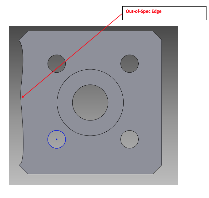 Yet using Positional tolerancing and tying the datums A and B into the final dimensioning scheme, the part may be just fine, removing the need to scrap our part. In other words, as long as the manufactured hole centers are within the Positional tolerance allowed, the part may be usable regardless of the poorly machined left wall.
GD&T is all about functional requirements. In the case shown above, deploying a Positional tolerance for the four hole locations greatly reduces the scrap rate for manufactured parts and would likely bring manufacturing costs down significantly.
Please contact Joel Pollet for any questions.


Leave A Comment