In this issue of our Metrology Minute, we will discuss how to resize section planes so that just the necessary geometry is displayed. This becomes extremely useful for very complex models where you want to draw the reviewer’s attention to a specific location on the model.
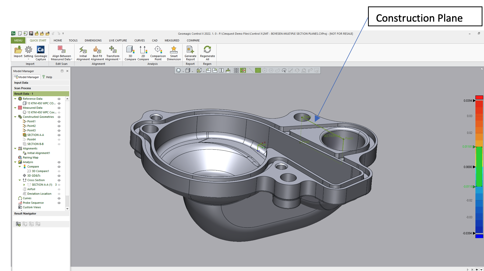
In order to do this, the first thing we needed to do, in our example below, was to create the plane that we planned to use to create the partial section. We identified these three points first as circle centers and then we fitted a plane through those points as shown below.
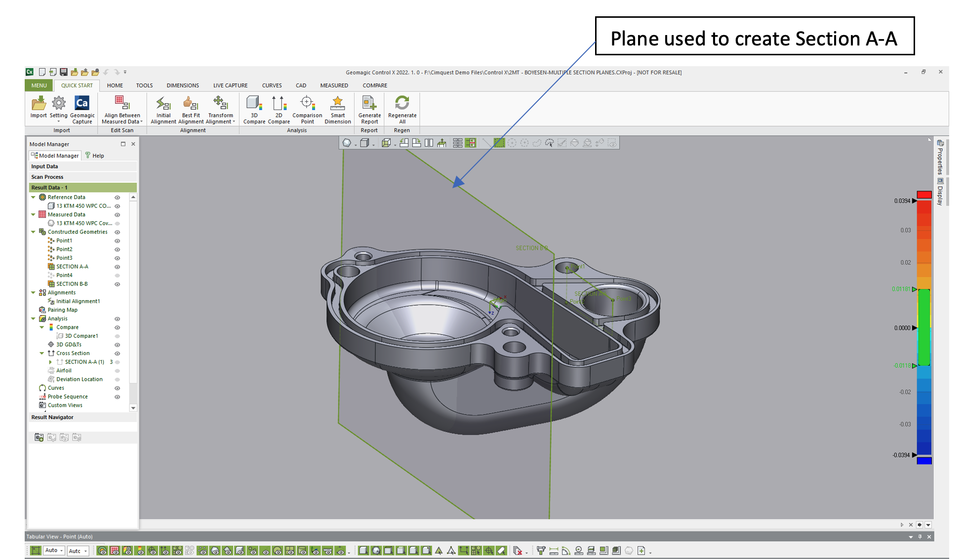
Next, we placed a point at the center of the large water pump cover radius and created an offset plane, parallel to our construction plane and passing through that point. This is the plane that was used to create the partial section.
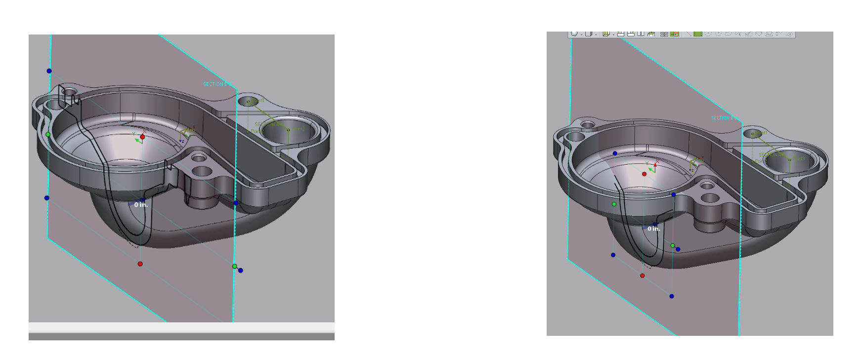
After we instructed Control X to create the 2D Section, plane control handles became available, enabling us to control just how much of the section was cut by the plane and exactly which cross-sectional geometry was shown. If we wanted to isolate just a single area where the large inlet was located, we could have reduced the size of the plane where just the geometry of interest was shown.
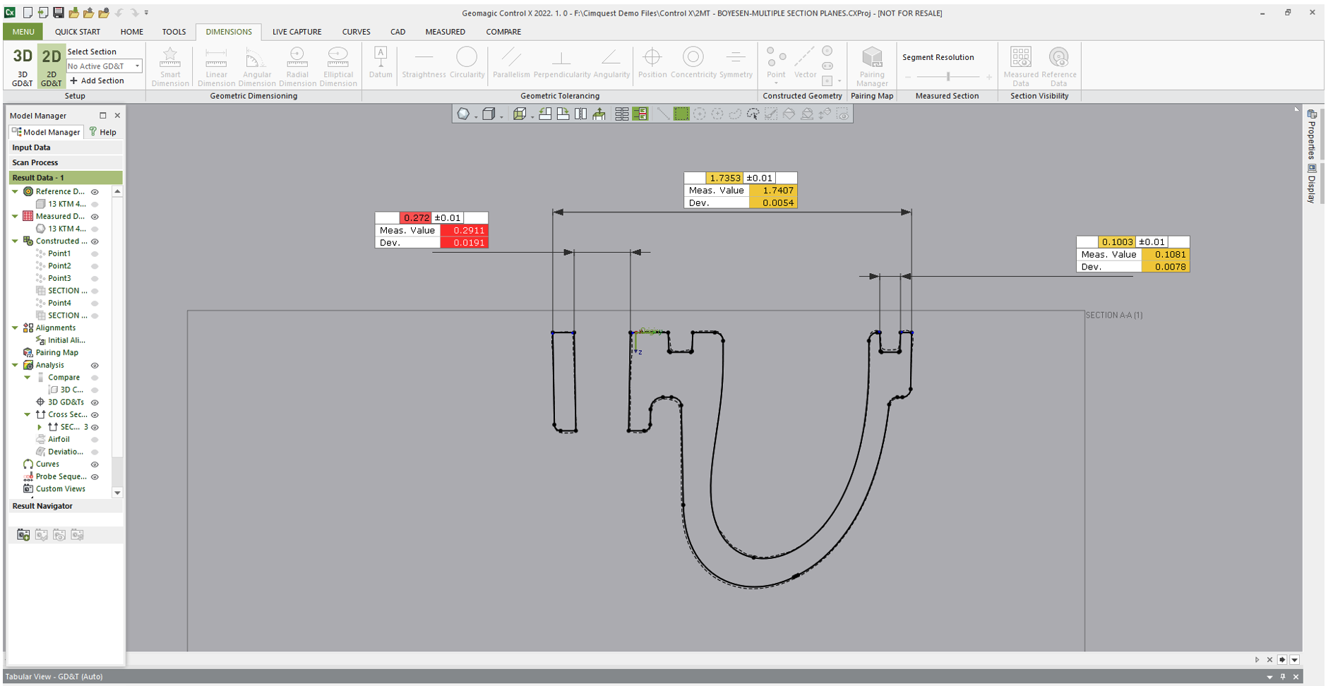
Fro here we were able to place the 2D dimensions onto the radii of interest. This allowed us to show the full solid model in the cross-sectional view and change the viewing status to transparent to get a clear picture as to the exact areas of interest this section is displaying.
We hope you found this Metrology Minute helpful. Please contact Joel Pollet with any questions.


Leave A Comment