In our last Metrology Minute post, we demonstrated how Control X can be used to extract feature size and location information directly from the scan, without the use of a nominal CAD model. With this route, a more traditional type of inspection could take place using just the scan of a manufactured part or assembly. We explained how a region’s model may be used to identify and measure analytic features, directly from a scan.
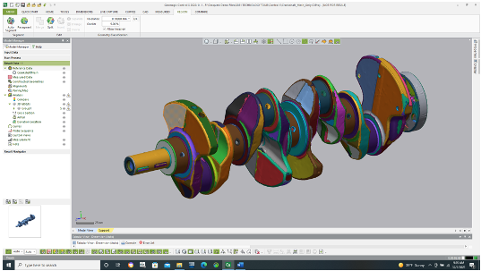
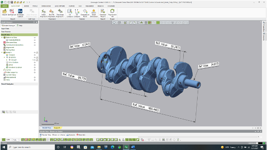
And can place dimensions onto the 3D mesh model to then compare results from 2D print dimensions which is a fairly common and traditional method of performing part inspections.
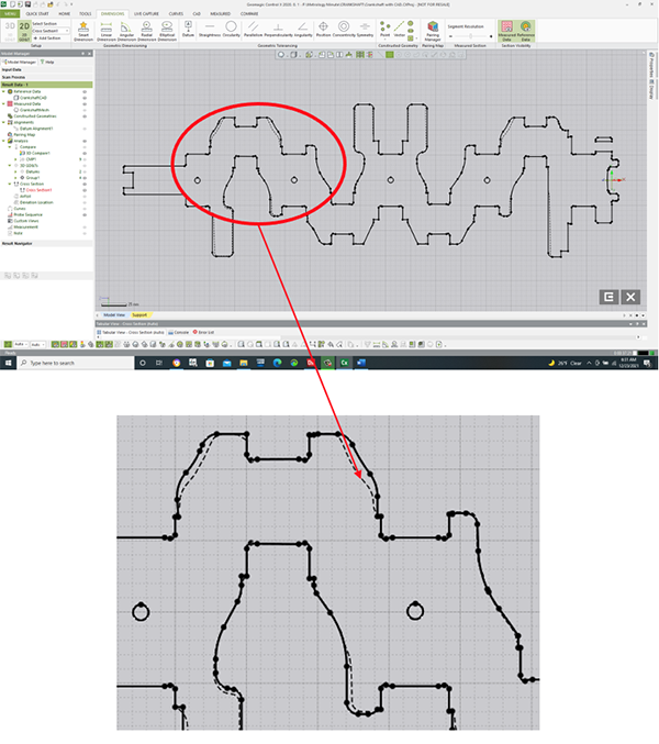
When the CAD model is present, however, Control X can also create 2D sections through a model and achieve the equivalent of a 2D drawing as well. As you see in the section view below, a plane is passed through the CAD model and aligned scan. The model is shown in solid, black font whereas the scan appears in dotted font.
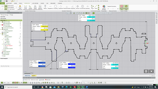
Finally, standard dimensions may be added to the 2D section, using the 2D dimensioning tools, comparing this metric crankshaft scan to its corresponding CAD model, but at a cross-section through the model.
Please reach out to Joel Pollet with any questions.


Leave A Comment