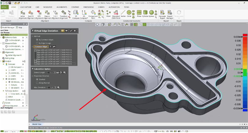
This blog post will discuss how to use the Virtual Edge Deviation Tool in Control X. It is often necessary to extract virtual edges of a part to compare them to the actual CAD model’s edge to ensure a part is within spec. Depending upon the resolution of the scanner, the sharp edges of a scanned part may be somewhat rounded or chamfered.
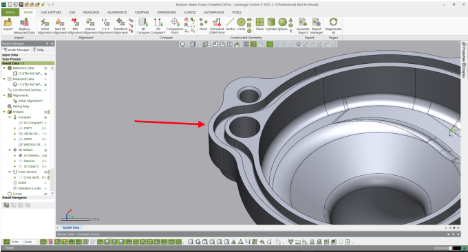
Consider the requirements of checking the outer edge of the part shown below to ensure it aligns properly with the mating part. In this post, we will explore running a Virtual Edge Deviation Analysis around the outer perimeter of the part.
CAD MODEL – Actual Sharp Edge
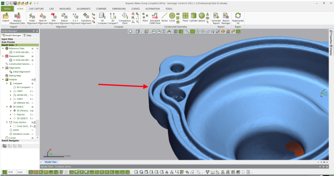
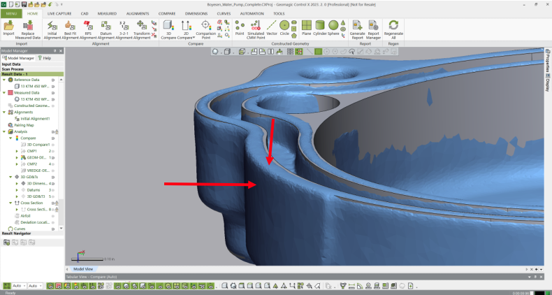
SCAN – Edges are rounded due to the scanner’s point spacing (aka resolution)
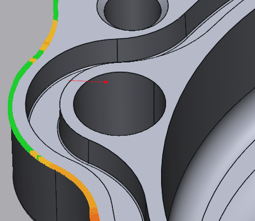
The virtual edge of the mesh would be where the thin rib top and outside walls of the manufactured part would meet, if extended. In the image below, we are showing the scan and CAD model after alignment. The red arrows are pointing to the flat surfaces that would be extended to determine the theoretical edge of the scan surface so it may be compared to the CAD model’s nominal edge.
Virtual Edge Deviation – Shown as a whisker plot
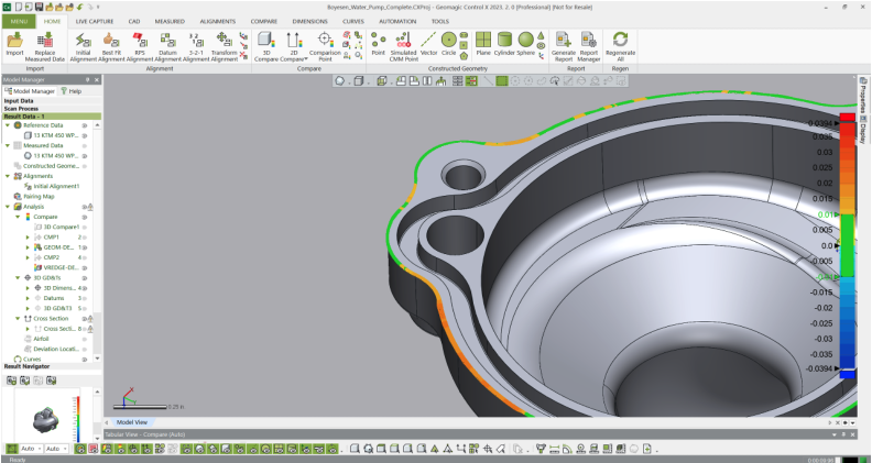
The whiskers are used to show the deviation from the actual CAD model’s edge and the theoretical or virtual edge distance. As with all color maps, the yellow/orange/red colors indicate trending to a full condition (i.e. the scan is “outside” of the CAD model) and light to dark blue colors represent an undersized condition.
The Whisker plot not only shows us where the outer periphery is in spec, but it also shows where it goes out-of-spec, on which side, and by how much. This is an extremely useful tool for this type of analysis requirement.
Please contact Joel Pollet with any questions.


Leave A Comment