Using a Portable Arm for Part Inspection
This blog post will introduce you to using a portable, 6-axis arm and powerful metrology software for part inspection. The software that we will be referring to is Verisurf and the 6-axis arm metrology software for part inspection is Master 3D Gage. Read on to learn how these tools are used.
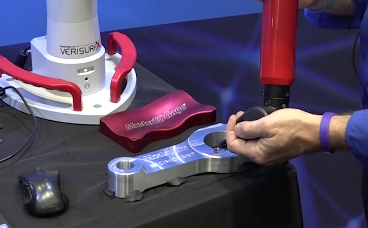
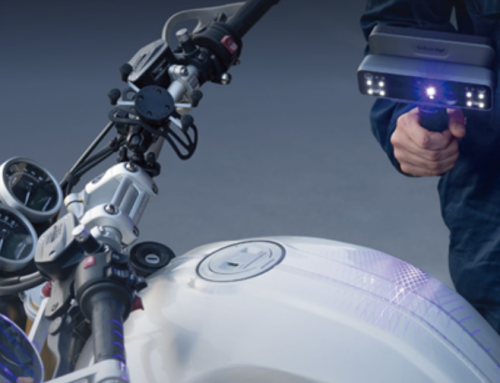
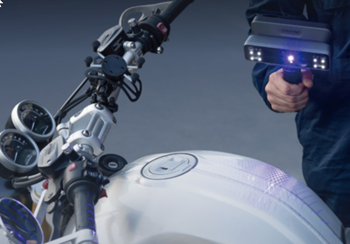
The Master 3D Gage is a 4-foot arm capable of measuring from very small to fairly sizeable parts using either a probe tip or scanning device. In this article, we will focus on probe-based inspection.
Verisurf software runs ‘inside’ of Mastercam, the most popular and widely used CAM software in the world. This enables both CNC part programmers and part inspectors to use the exact same User Interface to program as well as inspect parts. While this article explains Verisurf running the Master 3D Gage, the software could also be used to program manual and automated CMM’s, trackers, and even laser projectors. In fact, there are dozens of metrology devices that may be driven by Verisurf metrology software.
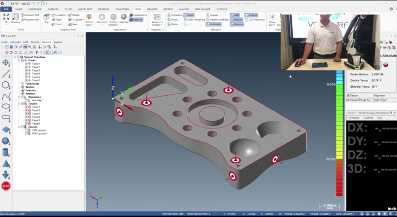
The first part of any inspection involves an alignment process. In this example, we placed six virtual targets onto the model to then be used for part alignment.
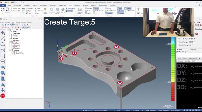
Using the Master 3D Gage, we triggered six selections by touching the probe tip to the model at the approximate target locations and clicking a trigger on the arm’s knuckle or the part of the arm that is held in the inspector’s hand.
The next target for selection will highlight, making it easy for you to achieve a good alignment.
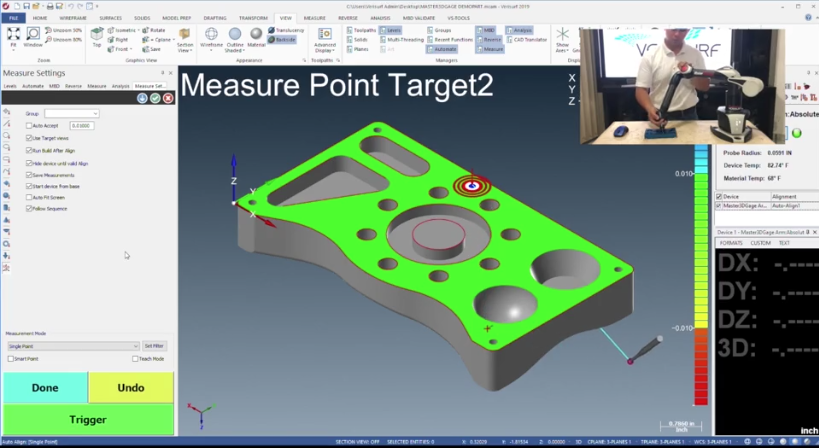
The type of alignment being performed is commonly referred to as a 3-2-1 or plane, line, point alignment where the first three picks define the plane, the second two picks dictates the line and the final pick is the last lock-down point, thereby tying down all degrees of freedom and aligning the physical part to the nominal CAD model.
Most Verisurf users prefer the target alignment approach but the ability to create and align by datums is also supported by Verisurf.
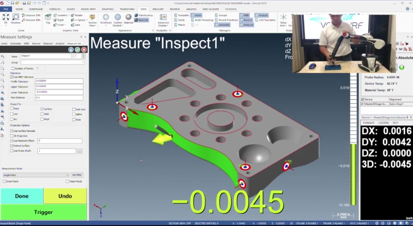
Once aligned, Verisurf automatically puts you into the BUILD module. BUILD allows you to touch or even drag the probe tip anywhere on the part and the software returns whether that surface is full or undersize from the nominal CAD model. BUILD offers an excellent tool, providing a quick snapshot as to part accuracy and is commonly used for laying out a fixture assembly and ensuring everything is located and aligned properly.
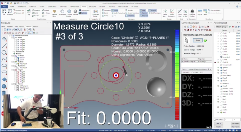
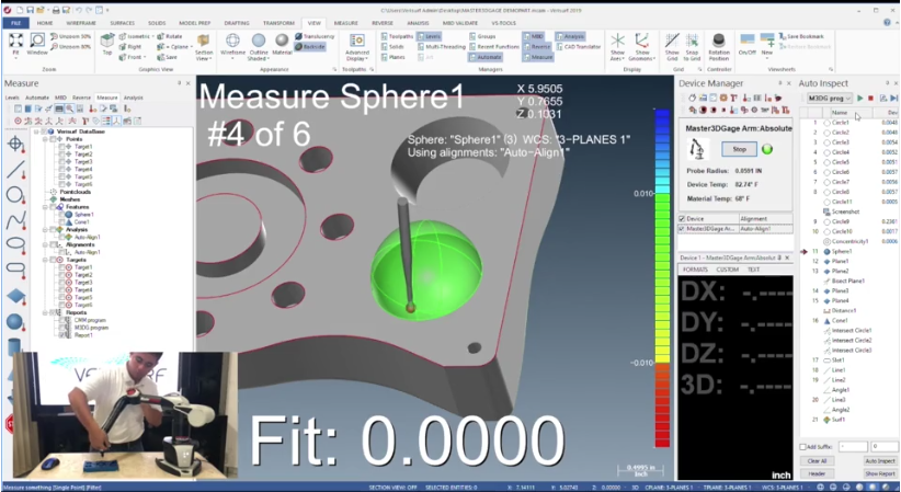
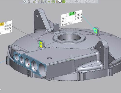
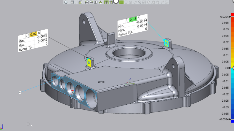
You can use the MEASURE module for interrogating part features as well as distances, angles, and so forth. If measuring a feature, the Form of the feature is displayed on the bottom of the screen after the measurement process is complete. For example, if measuring a plane, the Flatness of the plane would be displayed as the feature’s Form.
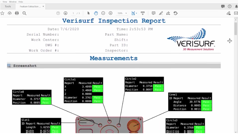
When all measurements are completed, customized inspection reports may be output in a number of formats, both to be useable in downstream operations such as Excel or CSV files or to a non-editable PDF format like the one shown below.
We hope you found this article on probe-based inspection informative. For more information on Verisurf products, please click the button below.

Leave A Comment