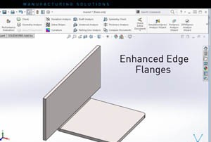
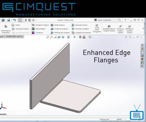
Working With SOLIDWORKS 2016 Edge Flanges
In today's episode of “What’s New in SolidWorks 2016” I’m going to show you an enhancement to sheet metal flanges that will allow you to create edge flanges that are longer than the edge to which they are attached. In previous versions of SolidWorks, an edge flange feature would default to the length of the edge of the sheet metal part with no options to manipulate the flange length. This is no longer the case. Now, you can drag the edges of the flange preview or input a value for the desired flange length. Let’s take a look at how it works . . . Open a flat sheet metal part. Go to Insert > Sheet Metal> and select the icon for Edge Flange. Next, select the edge where you’d like the flange to attach and in the Property Manager, under Flange Length input a value for the length of the flange. In this example we set the length to 40 mm. Under Flange Parameters, click Edit Flange Profile. In the graphics area, drag each vertical sketch segment so they extend beyond the adjoining sheet metal edge. In the profile sketch dialog box, click Finish, and see how the edge flange is added [...]

Cimquest Sponsors Villanova Race Car
Auto racing can be a fun and exhilarating sport. Reveled by dedicated fans and casual enthusiasts alike, the rapid acceleration, extreme speeds, and powerful roaring of engines delivers a rush of excitement unlike any other event. This year, Cimquest joined in the excitement through our sponsorship of Villanova University’s Formula SAE team, known as Nova Racing. Using 3D printing, we were able to help print a racing part designed by the team’s student engineers. This part was used in their final car design for the 2016 Formula SAE competition at Michigan International Speedway. The Formula SAE competition offers college and university students the opportunity to practice real world systems engineering through the design, fabrication, assembly and testing of formula-style race cars. Each year teams from over 100 institutions compete, working under the assumption that a manufacturing firm has hired them to develop a prototype race car for evaluation as a production item. Cars are judged in a series of static and dynamic events, including design, cost presentation, acceleration, autocross, skid-pad and endurance. Nova Racing has been competing in FSAE since 2008, building high performance cars from the ground up. The team encompasses a bright group of 25+ Undergraduate and Graduate engineers, all of [...]
Metal Hydroforming
Hydroforming is a demanding process, which uses pressure to force sheet metal to take the form of a mold. It was first adopted before World War II to form metal sheets using liquid as a soft punch. Used in low-volume manufacturing, hydroforming is favored for its ability to fabricate high quality complex parts with achievable weights up to 30% lower than standard units. It is primarily used in the automotive industry to produce engine cradles, sub frames, suspension components, and radiator support beams. Aerospace companies also use hydroforming to make airframe or engine components and the process is useful for prototypes, repair parts, and one-off custom parts. Using a variety of design methods, hydroform dies are produced by skilled laborers using CNC machines. However, there are drawbacks to conventional methods, including the high cost of raw materials, and the substantial lead times and machining costs associated with outsourcing. There’s also a general shortage of skilled labor in the workforce, which can heighten demand and inflate costs further. 3D printed Hydroform molds produced through fused deposition modeling can provide companies with remarkable time & cost savings. There is no limit to complexity and the design improvements made possible through FDM can contribute to the [...]

Björk Performs in 3D Printed Mask
The Icelandic music and film icon Björk has taken yet another fashion-forward step. Before an invitation-only audience at Tokyo’s Miraikan Museum, Björk performed in a 3D printed mask designed by MIT professor, designer and innovator Neri Oxman. Inspired by Björk’s most recent album, Vulnicura, Oxman, renowned in design circles for her use of 3D printing and biomimicry in particular, used 3D scans of Björk’s face to create digital interpretations of her bone and tissue structure. The customized design was brought to life using Stratasys’ unique full-color, multi-material 3D printing technology. Björk wore the 3D printed mask, entitled “Rottlace” (a variation of the Icelandic term for ‘skinless’), during the opening performance of the Tokyo leg of her ‘BJÖRK DIGITAL’ event series – a new virtual reality project from the musician running from June 29 to July 18, 2016. Björk wearing the Stratasys 3D printed mask during the opening performance of her ‘BJÖRK DIGITAL’ event series, the first-ever event to be broadcast live via 360-degree virtual reality streaming. Photo credit: Santiago Felipe. The event is the first to be broadcast live via 360-degree virtual reality streaming. Björk performed the single ‘Quicksand’ from her latest album to a backdrop of high-resolution images of the [...]
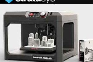
Industry Leading 3D Printing With MakerBot Replicator
Cimquest provides the leading Stratasys 3D printing solutions and our current promotions will give your company the leverage to go from concept to final product faster, cheaper, and with fewer mistakes. There’s never been a better time to enter into the additive manufacturing world to take advantage of the most powerful range of technology and materials. The Makerbot Replicator Essentials Bundle offers reliability, ease of use, and convenience all in one handy package. Enjoy a 3D printing experience that’s designed for you and your creativity. With the MakerBot Replicator Essentials Pack you have the freedom to try more ideas and create without breaking the bank. For a limited time, you can enjoy best in class 3D printing at a great, low price of $3,499.99. Save big on the package that includes: 1 MakerBot Replicator Desktop 3D Printer 1 additional MakerBot Smart Extruder+ Ten Pack of Large MakerBot PLA Filament One-year MakerBot MakerCare Protection Plan Build Plate Tape To find out more or purchase, call 866-277-8778 or click the button below. Financing is available! More Info
uPrint Professional Grade 3D Printers
uPrint offers professional grade 3D printers at consumer based prices. And now, for a limited time, you can get up to a 30% discount on them. Do you need a reliable 3D printer that delivers multiple design concept iterations and complex, durable prototypes - with exceptional repeatability and accuracy? Do you also want an advanced 3D printer that's built to last, comes ready to use with all the materials you need and operates virtually hands free, delivering you accurate parts, every time? You’re in luck because it is possible to get all of that, and more, from an office-friendly 3D printer! uPrint is the only proven professional 3D printer in its class that gives you: Unmatched repeatability, built to ISO 9001 standards, with high productivity and low maintenance The ability to print directly from your CAD file with GrabCAD Print - a 3D printing workflow application now available to use with uPrint 3D printers Dimensionally accurate and durable parts in even the most challenging geometries High quality parts made from engineering-grade plastics Proven long term reliability World class technical support available near you Take advantage of this special offer before September 30, 2016 by clicking the button below. Register Here [...]