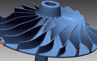
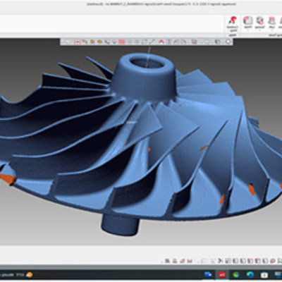
Deploying Design X Essentials for Reverse Engineering and CNC programming
Geomagic Design X Essentials can take a scan or point cloud from a scanner and use it as a template for reverse engineering the shape into a completely machinable Neutral or Kernel file (Step, ACIS or Parasolid). 2D Pockets that require 2-axis machining that include G02/G03 circular tool motion, G81/G83 point-to-point applications, etc. are all fully achievable, using Design X Essentials to create the model. The all-too-common Autosurface created by most reverse engineering software tools from mesh data is now a thing of the past. Autosurface algorithms generally create enormous, poor-performing models for machining that are somewhat unusable and not editable. They certainly cannot be used to machine analytic features that produce linear and circular motion for basic milling and turning operations. Design X Essentials produces fully usable neutral and kernel files. Resultant models will appear as if they were built using a CAD system. What about more complex machining? In the world of 3D surface machining, Lofted and Swept surfaces and the like, including Guide Curves may be built and 3-axis simultaneous tool motion can be created. In fact, full 4 and 5-axis parts or parts to be machined using 4th or 5th-axis positioning may also be created using Design X Essentials. [...]

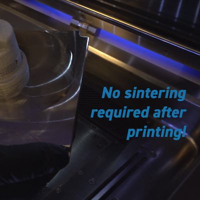
A MIM-Based Approach to Metal 3D Printing from Entry to Production: Session 3 – DSH – Webinar on Demand
A MIM-Based Approach to Metal 3D Printing from Entry to Production: Session 3 – DSH TechnologiesReplayed from a live webinar held on June 6, 2023 Check out the third of our 4-part webinar series, A MIM-Based Approach to Metal 3D Printing from Entry to Production. This time we were joined by DSH Technologies! The mission of this session is to help people understand what debind and sinter technology is all about. Let’s turn the black box into a glass box. DSH will walk through what the processing steps are, and how it functions and share some examples of successes and failures.

How to Remove Xact Metal DMLS Supports
This blog post will cover how to remove Xact Metal Direct Metal Laser Sintering (DMLS) supports from completed 3P-printed parts. It will explain the process of safely and effectively separating supports from the build plate, removing supports from your metal 3D-printed part, and cleaning up support touchpoints. You will first need to have the necessary tools ready, including a cutting tool such as a bandsaw or hacksaw to separate the part from the build plate and small handheld tools like needle nose pliers and flush cutters to remove the supports from the part. Safety is crucial when working with metal parts. Be sure to use safety goggles and gloves to protect yourself from debris and metal particles during this process. Using a bandsaw or a hacksaw, you will need to carefully cut the part off of the build plate, leaving the supports attached to the part. Once the part is cut off, use needle-nose pliers to grip the supports and gently twist or wiggle them to break them away from the part. Be cautious not to apply excessive force that could cause damage. After removing the supports, you may notice some residual material or sharp edges on the part. Use a file, rough [...]
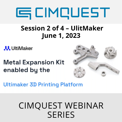
A MIM-Based Approach to Metal 3D Printing from Entry to Production: Session 2 – UltiMaker – Webinar on Demand
A MIM-Based Approach to Metal 3D Printing from Entry to Production: Session 2 – UltiMaker Replayed from a live webinar held on June 1, 2023 Check out the second of our 4-part webinar series, A MIM-Based Approach to Metal 3D Printing from Entry to Production. This time we were joined by UltiMaker! Metal Expansion Kit enabled by the UltiMaker 3D Printing Platform: Application Engineer Luis Rodriguez will walk you through the contents of the kit and the platform that enables you to create professional metal parts.
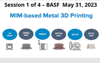
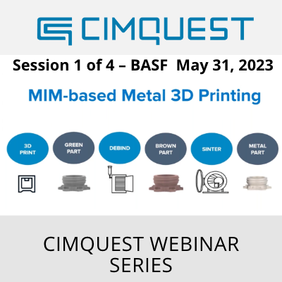
A MIM-Based Approach to Metal 3D Printing from Entry to Production: Live Session 1 – BASF – Webinar on Demand
A MIM-Based Approach to Metal 3D Printing from Entry to Production: Live Session 1 – BASF (Webinar) Replayed from a live webinar held on May 31, 2023 Check out the first of our 4-part webinar series, A MIM-Based Approach to Metal 3D Printing from Entry to Production. This time we were joined by BASF! BASF’s Ultrafuse® 316L and 17-4 PH metal filaments are designed for ultimate ease of handling and use on conventional Fused Filament Fabrication 3D printers. Learn how BASF leverages years of metal expertise, along with design considerations and partnerships, to make stainless steel 3D Printed parts both highly accessible and at an affordable cost of ownership.
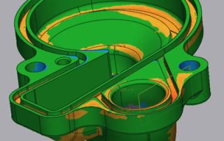
Creating Multiple Section Planes in a Single Command using Control X
In this blog post, we are going to demonstrate the creation of multiple section planes in a single 2D Section command using Control X. In a recent blog post, we created two planes where one passed through the center points of two holes and the second was a linear distance offset, away from the first. Now, we are going to explain how to create a new plane that is parallel to Section A-A where we can capture geometry from Section A-A plus capture and dimension an additional section slicing through the groove cross-section. To start off, first, turn off the color map so section A-A is easier to see. Then you can enter the 2D Cross-Sectioning tool and tell Control X you would like to create a cross-section, using the plane labeled as Section A-A. Select the Base Plane option and then select the plane called Section A-A. Your goal is to dimension this cross-section by constructing an additional plane somewhere that crosses the groove. Just remember that you can resize the plane to limit what is shown in the cross-section. Next, select the Multiple Cutting Plane checkbox and draw a line representing the second section plane for this exercise. The length of [...]