
Take Advantage of Section 179 and Save Money
Most successful businesses take advantage of legal tax incentives to help lower their operating costs. Did you know that you can immediately deduct the full purchase price of qualifying equipment and/or software? Section 179 of the IRS tax code lets businesses do just that. Much of the equipment businesses purchased to conform to COVID-19 restrictions will qualify for the Section 179 tax Deduction. Further, eligibility for the Section 179 tax deduction for 2020 is unaffected by any pandemic-related financial assistance a business may have received (e.g., PPP Loans.) In other words, if a company received a PPP loan or any other Pandemic-related assistance, they may still claim their Section 179 Deduction. 2020 Section 179 Deduction Limit for Businesses is One Million Dollars The Section 179 deduction for 2020 is one million dollars. This means U.S. companies can deduct the full price of qualified equipment purchases, up to $1,000,000, with a “total equipment purchase” limit of $2.5 million. The deduction includes both new and used qualified equipment. In addition, businesses can take advantage of 100% bonus depreciation on both new and used equipment for the entirety of 2020 Curious how much you can save with Section 179 on your own purchase? View the 2020 [...]
Nexa3D Partners with Siemens to Automate Additive Manufacturing
Siemens, the technology powerhouse in manufacturing, mobility and infrastructure automation, and digitalization, and Nexa3D, the maker of ultrafast polymer production 3D printers, today announced a collaboration designed to bring Nexa3D’s additive manufacturing production systems up to full Industry 4.0 preparedness. This partnership highlights both companies’ strong commitment to help additive manufacturing prepare for Industry 4.0 with innovative collaborations, open architecture, and predictive serviceability. Having worked side by side with automotive, aerospace, medical and industrial customers, Siemens and Nexa3D have proven the need to combine connectivity, digital twin sensing, and data acquisition to deliver 24/7, lights out predictive maintenance, process monitoring and print optimization to deliver polymer additive manufacturing solutions at scale on the factory floor. Under this collaboration, Nexa3D’s entire Quantum Laser Sintering (QLS) product line will be standardized to Siemens’ state-of-the-art factory automation and edge computing technologies. Nexa3D plans commercial delivery of its QLS-350 polymer production 3D printer powered by Siemens’ automation controls in the first quarter of 2021. “We are very pleased to join forces with Nexa3D and together unleash the power and potential of our products to create more resilient and sustainable supply chains,” said Tim Bell, Head of Additive Manufacturing, Siemens Industry, Inc. “Covid-19 underlined the incredibly rapid and [...]

Success with the New Ultimaker 2+ Connect 3D Printer
Ultimaker 2+ Connect for Education as well as Small and Medium-Sized Businesses Introducing the Ultimaker 2+ Connect 3D printer, the perfect printer for education and small businesses as the entry model to the Ultimaker ecosystem. Single Extrusion with a build volume of 223 x 220 x 205 mm (8.7 x 8.6 x 8 in) Down to 20 micron (0.001 inch) layer resolution Open filament system, compatible with glass and carbon fiber composites With efficient prototyping of simple single material applications, enterprises can increase product development speed with a quick and efficient 3D printing method. Educators can now facilitate multiple students to print with effortless operation in a low maintenance solution while improving your makerspace. Ultimaker delivers repeatable results, guaranteed ROI as well as easy-to-use software and an essentials platform that empowers educators providing them with stability and control. At home or in school, you have networking capabilities and easy touchscreen interface that make sending print jobs to the Ultimaker 2+ Connect with ease. For more information about this exciting new printer by clicking below. More info
Nexa3D Announces Two New 3D Printing Materials
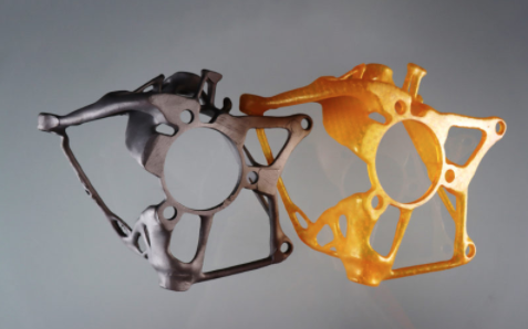
Nexa3D recently added xCast and xPRO410 to their 3D printing materials lineup. xCast, a new material tailored specifically for the production of precision investment casting patterns on the NXE400 3D printer. xCast is ideal for foundry series production of small, large and complex metal parts for a variety of aerospace, defense, automotive, oil and gas and heavy industry applications, offering a toolless, faster, and more accurate alternative to traditional pattern production. Watch the video below to learn more about xCast. xPRO41 is a rigid photoplastic that prints extremely high accuracy parts with exceptional surface finish. Formulated based on Henkel’s LoctitePRO410 polymer and optimized for Nexa3D’s NXE400 3D printer, this material is ideal for general purpose prototyping. xPRO410 is an affordable general-purpose material enabling multiple daily design iterations and same day on-demand parts for small and large product enterprises. This rigid material offers extremely high accuracy and exceptional surface finish that is ideal for service bureaus seeking to upgrade their services to same day and next day fulfilment. It enables the fast and accurate printing of parts for a wide range of form, fit and function designs and beautiful appearance prototypes. xPRO410 can be printed continuously on the NXE400 at speeds of up to [...]
Metrology Minute – Interpreting 3D and 2D Color Maps
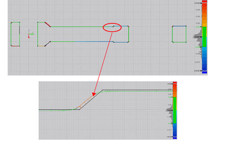
Let’s take a look at how to interpret 3D and 2D color maps using inspection software. Non-contact inspection software that is designed to show color maps will align the scan of a manufactured part with a nominal CAD model and actual manufacturing tolerances are revealed in a clear, easy to interpret fashion. Some products can show a blended color map whereby a color (typically green) represents a nominal tolerance. For the connecting arm color map in the example below, the green color is revealing the areas whereby the deviation from the scan to machined part is +/-.005”, the nominal value. Critical tolerances may also be shown that exceed nominal but reveal what is happening during the manufacturing process. In this case, critical tolerances are set to +/-.010”. Areas trending towards yellow, orange, then red are in between high nominal and high critical (between +.005” and +.010”). The closer to red, the further we are to approaching the critical tolerance ‘full’ (oversize) values. Conversely, the light to dark blue colors are showing where the model is trending between -.005” and -.010” or undersize values. By increasing the nominal tolerance to +/-.001” and the critical tolerance to +/-.005”, we get the results (below). You can [...]
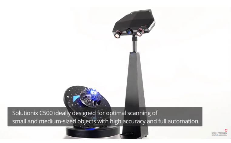
Introducing the Solutionix C500 3D Scanner
The Solutionix C500 structured light 3D scanner sets the standard for excellence and ease of use. The novice user can be up and running in minutes with single-click calibration and intuitive software deploying an extremely simple scanning process, from loading of parts to scan processing and scan exporting for downstream applications. Starting at just $40,000 for a single lens set or $52,000 for all four lens sets, the C500 covers a wide range of part size, accuracy, and resolution requirements making it a perfect choice for either a service bureau or a company with a wide range of part size scanning requirements. Utilizing an integrated and fully automated 3-axis rotary, tilt and swivel turntable, capturing all exposed surfaces for the scanner is a simple task. Typical scan processing algorithms including automatic scan alignment, global alignment, merging, and saving off the results in an automated fashion make the C500 perfect to use for batch processing of scans for an automated inspection operation. Whether scanning for reverse engineering, metrology, 3D Printing, or other applications, the C500 sets the standard for quality and ease-of-use and with all four lens sets, supports from very small to fairly large part sizes. Click the button below for more details [...]