Call Us Today! 1866.277.8778|sales@cimquest-inc.com

Tech Tips

8 11, 2017

SolidWorks 2018 UI Enhancements

By |2017-12-29T08:46:41-05:00November 8th, 2017|Categories: SOLIDWORKS, Tech Tips|0 Comments

SolidWorks 2018 is now out to the public so let’s take a look at five new enhancements that will allow you to get better acquainted with the User Interface of this release. Right off the bat, when you start up SolidWorks, you’ll notice that there is a new Welcome Dialog Box. It’s a one-stop shop for functionality that used to be found in the Task Pane. For example, the Home tab allows you to open [...]

11 10, 2017

Using SolidWorks PMI for Final Inspection

By |2017-12-21T08:58:41-05:00October 11th, 2017|Categories: SOLIDWORKS, Tech Tips|0 Comments

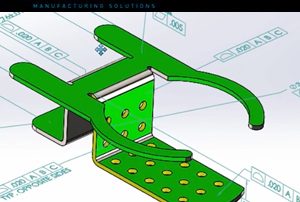
Let’s discuss two pieces of software that work really well together in the 3D part inspection world: SolidWorks, and Control X. SolidWorks is one of the leading CAD tools in today’s design and manufacturing world. One of its advantages is that it offers you the opportunity to create a 3D annotated model. This can include things such as explicitly-specified dimensions, tolerances, 3D GD&T, surface texture symbols, finish requirements, and so on. This 3D annotated model [...]

25 09, 2017

Mastercam 2018 Viewsheet Improvements

By |2017-12-21T09:05:55-05:00September 25th, 2017|Categories: Mastercam, Tech Tips|0 Comments

There are several improvements to Viewsheets in Mastercam 2018. In previous versions, the Viewsheet tools could at times be hard to set up, but now in Mastercam 2018 the new Quick Add button makes them easy to create and the bookmark tools on the view ribbon help save changes quickly. Look in the configuration file to see all the settings that Viewsheets can capture. Viewsheets can be extremely helpful if you do multi-plane milling or [...]

20 09, 2017

Reverse Engineering a 3D Pipe

By |2017-12-21T09:14:21-05:00September 20th, 2017|Categories: 3D Scanning, Tech Tips|0 Comments

This blog article will illustrate how to extract the centerline of a 3D pipe with compound angles. Extracting the centerline of a 3D pipe that contains angles in 2 dimensions is not that complicated. However, when you have compound angles, and the tube is bending in the X, Y, and Z directions simultaneously, extracting the centerline can be quite challenging. For example, below we have a prototype of ½ of a bicycle handle, printed on [...]

18 09, 2017

Mastercam 2018 Plane and View Systems Options

By |2017-12-21T09:12:26-05:00September 18th, 2017|Categories: Mastercam, Tech Tips|0 Comments

There are some new options available in the plane and view systems of Mastercam 2018. In previous Mastercam versions, there were only seven default system planes and their corresponding graphics views available to choose from. Now in Mastercam 2018, two new selections have been added which can be picked instantly and they can also be commanded relative to a custom WCS or added in the relative creation menu. Let’s compare the plane managers of Mastercam2017 [...]

13 09, 2017

SolidWorks 2017 3D Offset on Curved Surfaces

By |2017-12-21T09:09:27-05:00September 13th, 2017|Categories: SOLIDWORKS, Tech Tips|0 Comments

There is new functionality in SolidWorks 2017 that allows you to offset 3D curves on a surface. Offsetting 2D geometry is very efficient. It allows you to quickly grab 2D geometry and create a same shape contour with a specified gap distance. However, when working with 3D sketches containing 3D curves, it’s not as simple. As of SolidWorks 2016, many steps were required to accomplish this task. Now in SolidWorks 2017, it got a whole [...]

30 08, 2017

CMM Inspection without a Master Part

By |2017-12-22T08:21:20-05:00August 30th, 2017|Categories: 3D Scanning, Tech Tips|0 Comments

Have you ever needed to inspect parts in a CMM, without having a master part? Automated CMMs can be a great time saver when inspecting parts on the shop floor. Traditionally, a master part is measured to generate a master data set. The same routine is then automated and used to measure each production part. Each production data set is then compared to the master data set to determine the actual size of the part [...]

21 08, 2017

Defining Custom Tools in DXF Files for Tool Manager

By |2017-12-22T08:23:35-05:00August 21st, 2017|Categories: Mastercam, Tech Tips|0 Comments

If you run into problems where your custom tool geometry in a DXF file is not accepted into the Tool Manager you should ensure that your customer tool geometry meets all the following criteria: Geometry must be drawn horizontally, in the upper two quadrants, at or above the X axis. No entities can have a negative Y value. Geometry must be flat (at Z0) in Top view. A closed profile of half the tool shape [...]

Go to Top