Desktop Metal Live Sinter produces quality parts that meet form and dimensional tolerances right out of the furnace, in one or two iterations.
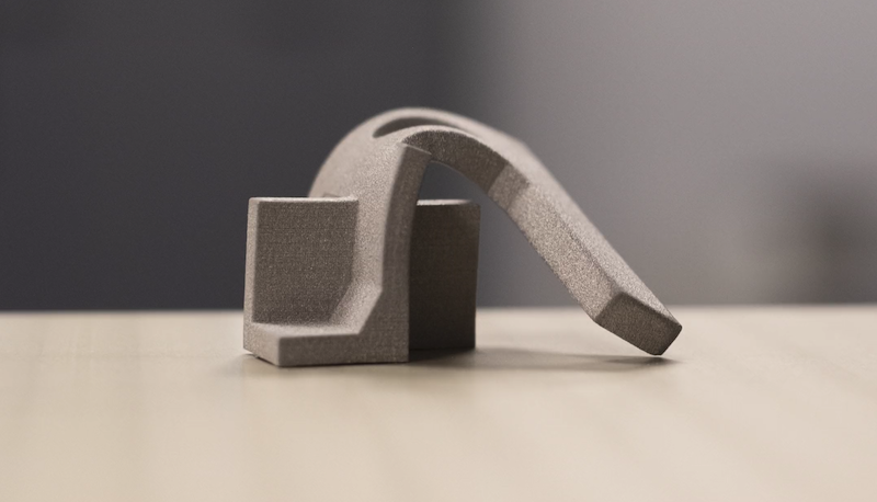
Today we’re going to show you an effective way to ensure that metal 3D-printed parts meet form and dimensional requirements right out of the furnace. Although metal 3D printing has many advantages, it can be challenging to predict the final part geometry due to the many physical forces introduced during the sintering process. The part is pushed and pulled in different directions, due to significant forces caused by gravity, friction, and uneven shrinkage due to density variations. This in turn may lead to deformation, warping, cracking, slumping, and parts that emerge from the furnace out of form and out of tolerance. It can quickly become a guessing game.
Currently, manufacturers must rely on best practices and the intuition of a relatively few engineers who have hands-on experience with sintering, in an attempt to get good parts right out of the furnace. This can be a time-consuming, iterative process, before achieving the desired results.
In contrast, Desktop Metal has taken a different approach. They have developed a first-of-its-kind, multi-physics simulation, and compensation software, that enables one to produce straight, defect-free, and accurate parts right out of the furnace. This software is known as Live Sinter.

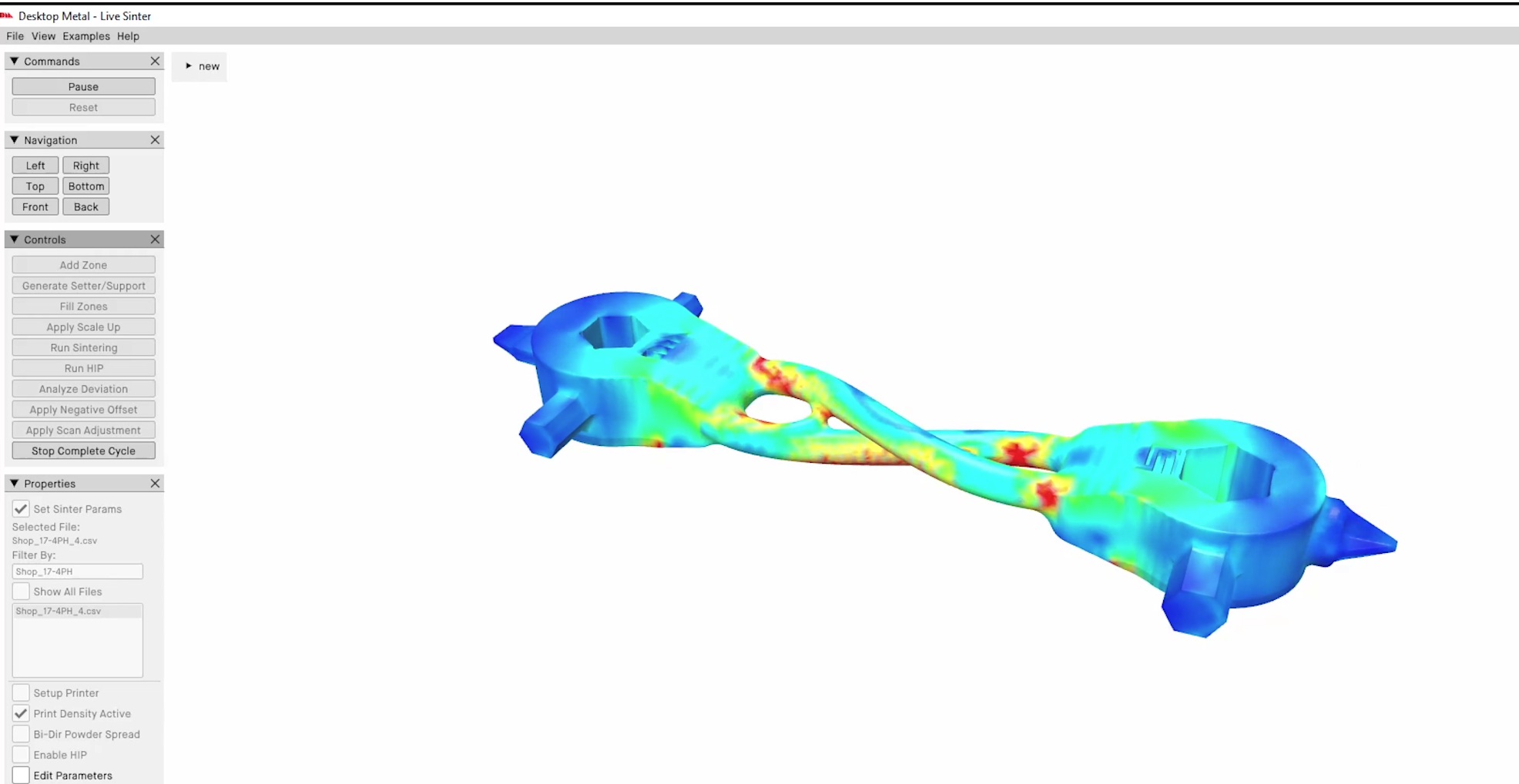
Live Sinter simulates the shrinkage and distortion of a metal part during sintering and predicts what the final shape will look like. It does this by using a meshless FEA engine, which performs periodic static stress analysis with time-varying contact surfaces. While the simulation of the sinter cycle is still running, you are able to visualize minute-by-minute temperature changes and shrink rates.
At the end of that simulated sinter run, the software takes the final distorted geometry and generates “negative offset” geometry to compensate for the distortion. This “negative offset” is then used as the “starting point” for the next sinter simulation cycle.
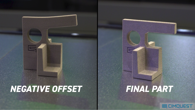
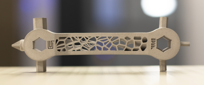
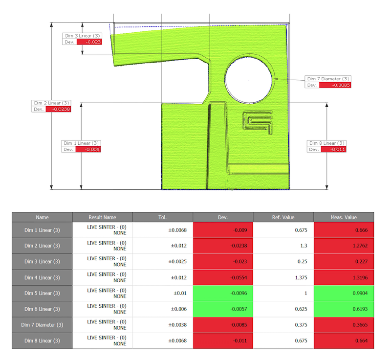
This process continues until the final “negative offset” geometry converges with the nominal CAD geometry. At this point, Live Sinter can export a high-quality, simulation-vetted, print-ready file. You can see in the example below that the non-simulated part failed most of the dimensional requirements.
 In contrast, the Live Sintered version fell well within the required tolerances right out of the furnace.
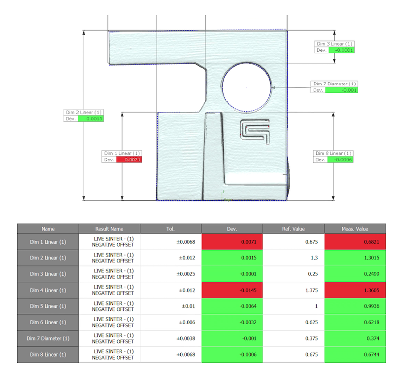 If a higher level of accuracy is desired, the previously simulated part can be 3D scanned and fed back into Live Sinter for an additional iteration. The software will analyze what it had predicted, compare it to the actual results, and then make further tweaks to generate a refined print-ready file. Using this “scan-based adjustment method”, parts will generally fall within 1% of the nominal dimensions.
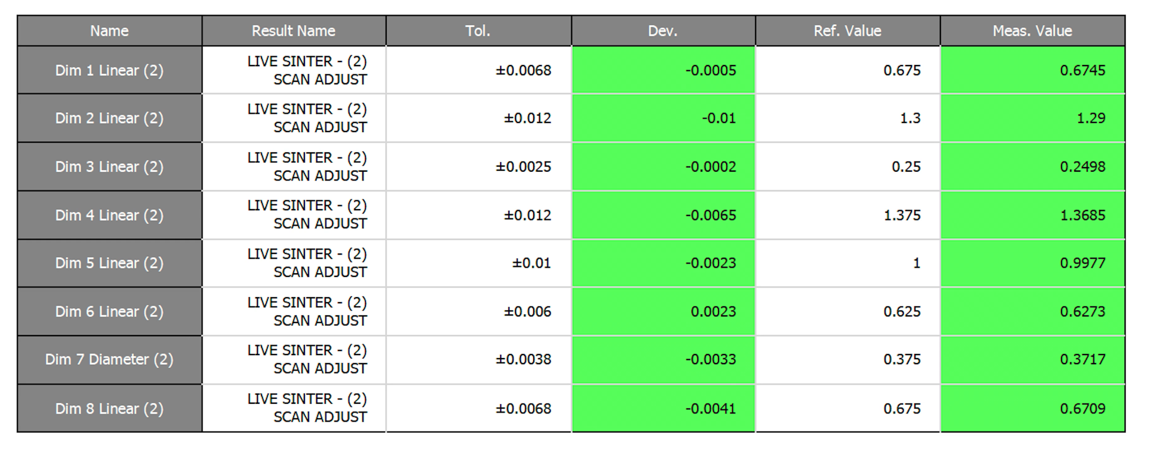
Let’s continue with the same part mentioned earlier. We know it met dimensional criteria after passing through the first iteration of Live Sinter. That being said, it did not pass the GD&T criteria. However, after scanning it and running a second iteration of Live Sinter, not only did all the dimensions fall within the 1% tolerance range, but all of the GD&T criteria passed as well. A definite improvement!
Desktop Metal’s proprietary software takes a very complex problem and provides a simple solution. By predicting multi-physics behavior, and compensating geometry based on actual results, one can produce good quality parts that meet form and dimensional tolerances right out of the furnace, in one or two iterations. Please be sure to sign up for our 2 Minute Tuesday video series to receive tips and tricks like this one in video form every week. More info at the button below.

Leave A Comment