Why would one want to use a Maximum Material Condition for a true positional callout for clearance holes?
Maximum Material Condition or MMC in GD&T is added to the GD&T symbol. The symbol is shown below.

In this example, we have a .137 diameter clearance hole that is defined as .137 Rad +/-.010”. Let’s assume the hole is manufactured (drilled) and inspected and it comes out as a .1303 radius, placing it .0067 undersize.
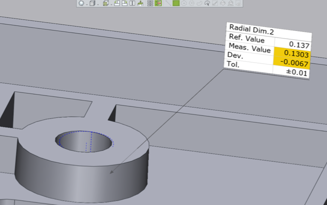
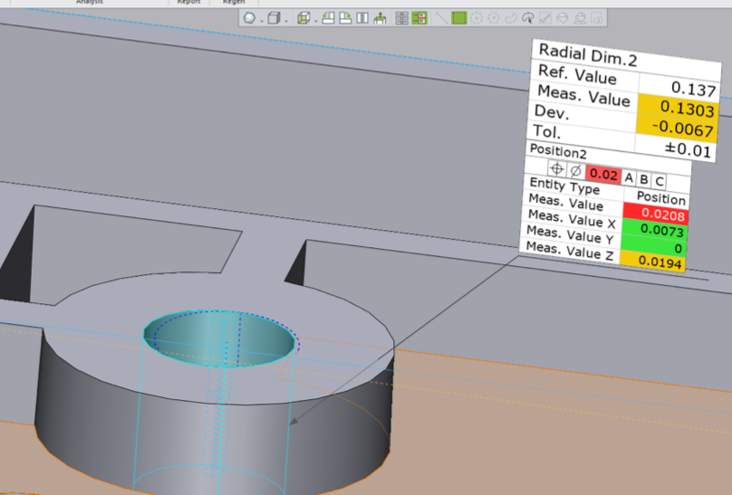
There is a True Position callout of .020” for this clearance hole to datums A, B, and C without a Maximum Material Condition callout. By going this route, the dimension fails.
The goal of any design is to provide the manufacturing engineer with as much tolerance as possible to still produce a good design that maintains the designer’s intent.
If we just go by the True Position Callout for the example above with no MMC specified, the dimension fails and the part would be rejected. If we consider the nominal hole size of .137, the MMC hole based on this dimensioning scheme would be .127” (or .137” minus .010”). This number represents the MMC for this clearance hole based upon the callout. This would represent the hole with the most material remaining yet still passing inspection.
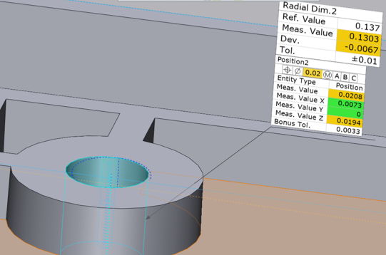
By adding MMC to the True Positional callout using a .020” tolerance, we are able to then add a “bonus tolerance” to the .020” to increase its value and enable the measured hole size to pass inspection.
In this case, Control X reports that the bonus tolerance is .0033”, enabling us to add this value to the tolerance value and thereby bringing the hole’s True Position into an acceptable tolerance.
Please contact Joel Pollet at Cimquest if you have any questions.


Leave A Comment