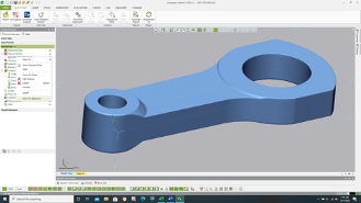
While most inspection software will use a nominal CAD model during the inspection process for comparison of manufactured features to exact CAD features, Control X can perform a feature-by-feature analysis without utilizing a CAD model. This can come in very handy when a CAD model doesn’t exist for inspection and just a 2D drawing is used. The first step is to import just the mesh file or point cloud into Control X. As a reminder, mesh files go into the MEA (Measured) node and CAD or nominal models end up in the REF (Reference) node. Since the system will assume the mesh or point cloud should be the MEA for the upcoming inspection, that is the node where the polygonal file ends up. We need to use the Model Manager and transfer the mesh to the REF node, indicating that no CAD model will be used and just the mesh will be inspected.
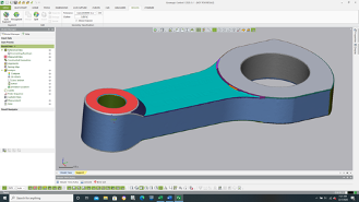
Next, we need to create Regions on the model so the software can identify features. Once Regions are created, you can measure any of the Region Features as if they come from a solid model and not a mesh or point cloud. Regions are identified by color, as depicted below. Planes, cylinders, and other measurable analytic features are color-coded, making it easy to isolate features for size and point to point measurements.
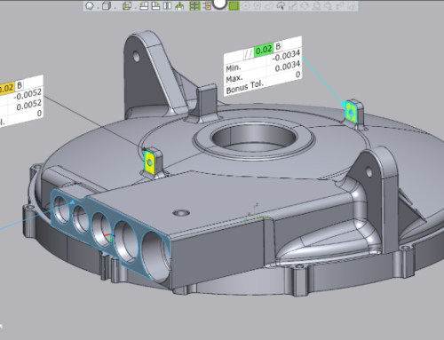
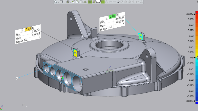
Once the Regions are created, you can read the 2D print and dimension the Region’s model to check for feature size, distances, angles, etc. This deploys more of a manual approach to inspection but does provide an avenue to inspect manufactured parts when no CAD model exists.
For any questions or comments on this month’s Metrology Minute, please contact Joel Pollet by clicking the button below.


Leave A Comment