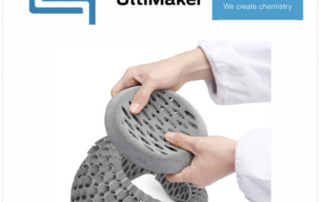
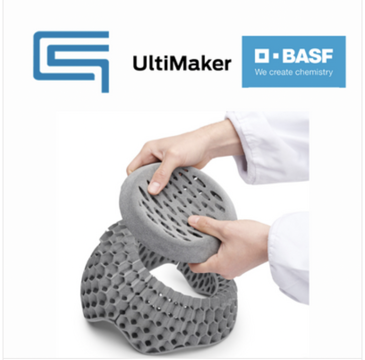
Explore Metal 3D Printing with BASF, UltiMaker & DSH
Come join Cimquest, BASF, UltiMaker & DSH Technologies for an educational seminar on Metal Additive Manufacturing! Thursday, February 16, 2023, 8:30 AM – 12:30 PM EST Cimquest headquarters 3434 Rt 22West Suite 130 Branchburg, NJ This seminar will focus on how it’s possible to get into metal 3D printing with an accessible cost of ownership. It begins with an introduction of the Ultrafuse® 316L & 17-4 PH metal filaments developed by BASF for use with conventional Fused Filament Fabrication (FFF) 3D printers. The 3 step workflow will be explained as well as why BASF chose Ultimaker and DSH Technologies as partners for this end-to-end process. During the presentation, several applications will be showcased including; tooling, jigs and fixtures, prototypes and functional. In the seminar we will dive into the following questions: How does this technology work? Would this solution fit my business needs? What types of parts can I print? How does post-processing work? Why should I care about this solution? How is it going to benefit me? You will also have the opportunity to participate in a Q&A session at the end of the seminar for any other questions you need answering! Once the seminar is complete, you will have the opportunity [...]

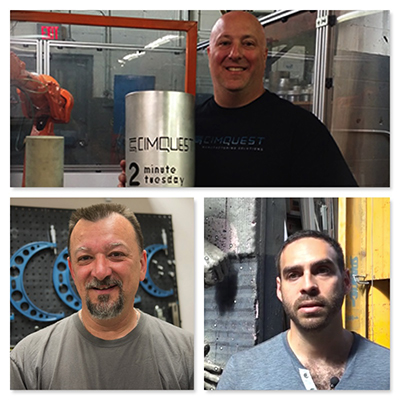
Calling All Our Amazing Customers
We are currently looking for customers that would like to be featured in our 2023 marketing efforts. We would love to showcase your real-life, positive experiences. These stories can be effective for promoting your services and businesses as well as ours. Depending upon your applications, Cimquest may feature you in any one of our various marketing efforts including a live webinar, a case study, a customer testimonial, or even a featured 2-Minute Tuesday video. We believe that our customers are the top priority, and we would love to be able to help generate more engagement and views for your business! This could offer you some great exposure. If you are having success with our products and services and have a story to tell, please email us by clicking below. We look forward to hearing from you and learning all about your experiences and business. Contact Us

Entering 2023 – A Letter from our CEO
We all made it through another year! With 2022 in our rearview mirror I would like to take this opportunity to thank you for choosing to partner with Cimquest! We at Cimquest do not take our relationships lightly. Each and every day I know that we owe it to our customers and partners to prove our continued value to your businesses. It is our job to make that happen! The world is becoming more and more complicated every day. I seem to wrestle with the world that was and the world we are to become. The "world that was" contained very valuable substance. You could easily reach a live person at any business entity that you chose to patronize. The "world in which we are becoming" is one where the personal touch has been lost or relegated to chatbots, AI’s, FAQ’s, self-assisted forums, and at best a maze of call center menus that lead to dead ends. Someday the technology will mature and our AI will support your AI while we all are drinking Margaritas on the beach. However, for now, we are here for you! This reminds me of the old joke where the factory of the future is run by just [...]

Metrology Minute – Control X Plot Comparison
The Control X Plot Comparison Tool will analyze the thickness, curvature, and angle of Measured data (point cloud or mesh) and uses color mapping to display the results. You can also pinpoint specific point locations on the model to return actual values for the plot being reviewed, at those specified locations. One of the unique aspects of this tool is it does not require Reference data. All calculations utilize a single Measured mesh or point cloud for the analysis. Measuring Wall Thickness If you want to ensure the top blade edge of the turbine shown below never drops below a .050” wall thickness, you can deploy the Plot tool, and use both color maps and selected points. Control X can return the wall thickness at specified locations. For the image shown below, the min and max Range is set to +/-.050”, meaning if the color is dark red, the wall thicknesses for each blade is, at least .050” thick. You can see where one of the analysis points near the blade’s edge where the thickness does drop below .050”. By increasing the Min/Max Range to +/-.100”, you can see how the color map now appears much more revealing as to what is actually [...]
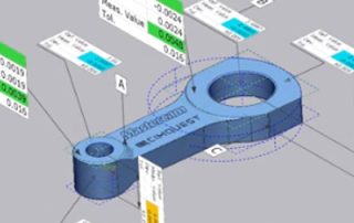
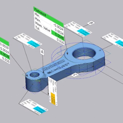
Product Manufacturing Information (PMI) Using SOLIDWORKS & Control X
This blog post will explore the Product Manufacturing Information (or PMI) model generated in Solidworks and how it may be used to automate the inspection process in Control X. PMI is a fairly new tool that enables manufacturing information to remain with CAD models through downstream applications. Traditionally, the Control X user would need to enter all dimensional and datum information manually. By implementing PMI, all manufacturing information flows seamlessly from CAD to inspection, thereby accelerating the complete process and minimizing the risk of entering wrong values. The manufacturing information controlling the inspection process is entered just one time and is used throughout the design and inspection process. In this example, we have a Solidworks model of a connecting arm. The model contains PMI information. Specifically, it shows the features that will be used as datums, GD&T callouts for Flatness, and standard dimensions with tolerances. In Control X, we can import the Solidworks model containing the PMI information. The import shows if the three datums, six dimensions with tolerances assigned, and two GD&T callouts, along with the native CAD model, have all successfully imported into Control X. Control X refers to the nominal CAD model as the REF or Reference data and the [...]

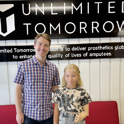
Unlimited Tomorrow Makes High-tech Prosthetics More Accessible
Medical device startup develops and manufactures its TrueLimb® robotic prosthetic device by leveraging HP’s MJF 3D printing technology and working with partners including ABCorp and Singularity Group. Learn how medical device startup Unlimited Tomorrow recently partnered with ABCorp to additively manufacture components for the TrueLimb® robotic prosthetic. ABCorp operates a fleet of HP Jet Fusion 5210 3D printers and utilizes them to provide Unlimited Tomorrow with more consistent parts, faster and less expensively—enabling them to scale and ultimately fulfill their global mission of augmenting the human body with better technology. Download the case study below. Thank you for Signing Up Download the Desktop Metal Material Guide Please complete this form to access the PDF Download. Please correct the marked field(s) below. * 1,true,6,Lead Email,2 1,false,1,Zip Code,2 *Required fields Note: It is our responsibility to protect your privacy and we guarantee that your data will be completely confidential.