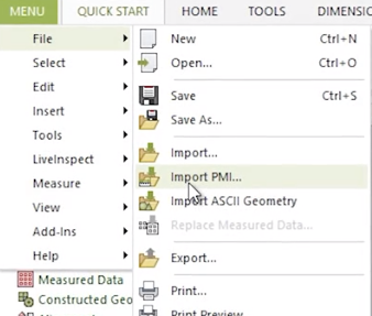
This blog post will explore the Product Manufacturing Information (or PMI) model generated in Solidworks and how it may be used to automate the inspection process in Control X. PMI is a fairly new tool that enables manufacturing information to remain with CAD models through downstream applications. Traditionally, the Control X user would need to enter all dimensional and datum information manually. By implementing PMI, all manufacturing information flows seamlessly from CAD to inspection, thereby accelerating the complete process and minimizing the risk of entering wrong values. The manufacturing information controlling the inspection process is entered just one time and is used throughout the design and inspection process.
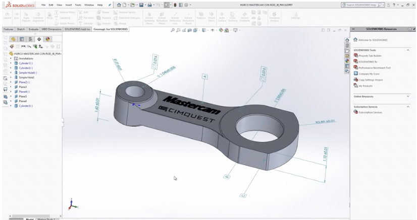
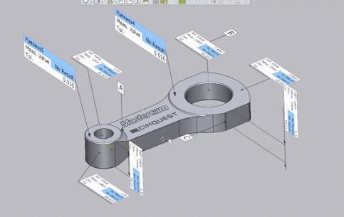
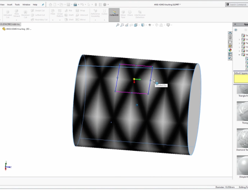
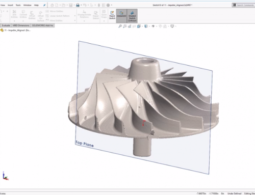
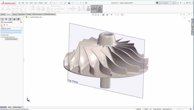
In this example, we have a Solidworks model of a connecting arm. The model contains PMI information. Specifically, it shows the features that will be used as datums, GD&T callouts for Flatness, and standard dimensions with tolerances. In Control X, we can import the Solidworks model containing the PMI information.
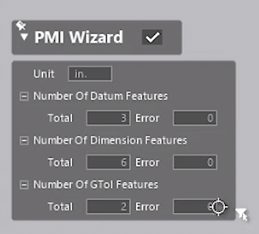
The import shows if the three datums, six dimensions with tolerances assigned, and two GD&T callouts, along with the native CAD model, have all successfully imported into Control X. Control X refers to the nominal CAD model as the REF or Reference data and the scan of the manufactured part as the MEA or Measured data.
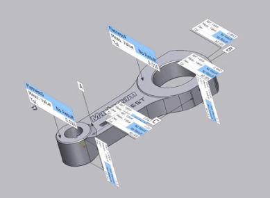
The text boxes have carried the dimensional information and the tolerance information over from the Solidworks model. However, note how “No Result” is shown for the Measured value.
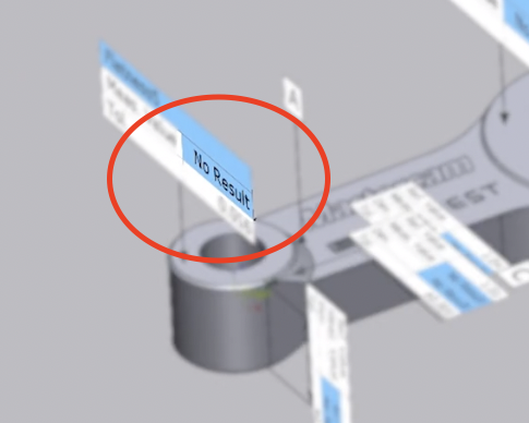
This is because the scan has yet to be imported and aligned to the nominal CAD model. In order to do this, you need to position the model so the values are easy to see after import and alignment.
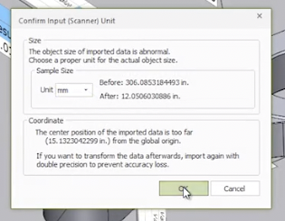
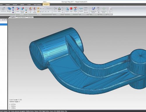
Next, you can import the scan of the manufactured part and specify its units since scan data is generally unitless.
After that, align the scan to the nominal CAD model based upon the datums supplied by Solidworks. All dimensional and GD&T Callouts are now evaluated and displayed in the text boxes.
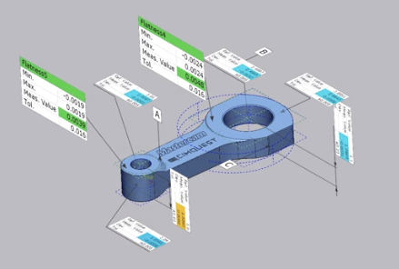
In this case, the dimensional data is automatically broken up into two sections based on the Solidworks planes they were created in.
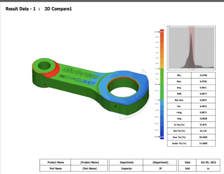
An inspection report is also created in which additional inspection tools may be deployed such as color maps, whisker plots, geometric deviation boxes, and much, much more.
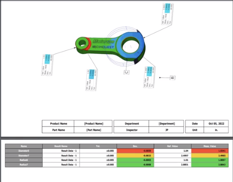
In the final report, the results are shown in a graphical format and are followed by a spreadsheet representation. Color coding is used to further highlight the dimensional values that are within an acceptable tolerance. This data may also be exported in formats such as XML and CSV, making them usable for other applications.
As you can see, using PMI allows for a seamless transfer of manufacturing information between unrelated products, thereby reducing the probability of error and drastically speeding up the inspection process.
Leave A Comment