Call Us Today! 1866.277.8778|sales@cimquest-inc.com

3D Scanning

4 11, 2020

Metrology Minute – Interpreting 3D and 2D Color Maps

By |2020-11-04T08:13:58-05:00November 4th, 2020|Categories: 3D Scanning|0 Comments

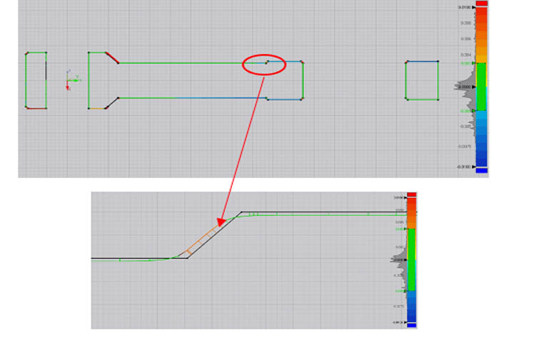
Let’s take a look at how to interpret 3D and 2D color maps using inspection software. Non-contact inspection software that is designed to show color maps will align the scan of a manufactured part with a nominal CAD model and actual manufacturing tolerances are revealed in a clear, easy to interpret fashion. Some products can show a blended color map whereby a color (typically green) represents a nominal tolerance. For the connecting arm color map [...]

30 09, 2020

Solutionix 3D Scanner

By |2020-09-30T08:57:26-04:00September 30th, 2020|Categories: 3D Scanning|0 Comments

Cimquest recently added a new 3D scanner to our portfolio. It’s called the Solutionix C500 and it is a structured Blue LED scanner. It’s designed to be user friendly so that both novices and experts can operate it with ease. It comes with the scanner, the stand, and an automated rotary 3-axis turntable. It combines well-written, intuitive software with simple, easy-to-learn calibration, scanning, and post-processing routines. Here are some of the key features . . [...]

9 09, 2020

How To Choose Your First 3D Scanner – Part 3

By |2020-09-09T08:15:36-04:00September 9th, 2020|Categories: 3D Scanning, 3d Scanning & Reverse Engineering|0 Comments

Welcome to Part 3 of our Metrology Minute series. In parts one and two of this three-part series, we explained several key components in choosing your company’s first scanner; Field of View (FOV), Accuracy, and Resolution are the first considerations. For a quick review . . . Field-Of-View (FOV) is the volume envelope that your scanner can ‘see’. Ideally, the FOV is large enough to scan your largest parts yet still maintain the accuracy and resolution [...]

21 08, 2020

Verisurf for Metrology

By |2020-08-21T08:13:35-04:00August 21st, 2020|Categories: 3D Scanning, 3d Scanning & Reverse Engineering, verisurf|0 Comments

Using a Portable Arm for Part Inspection This blog post will introduce you to using a portable, 6-axis arm and powerful metrology software for part inspection. The software that we will be referring to is Verisurf and the 6-axis arm metrology software for part inspection is Master 3D Gage. Read on to learn how these tools are used. The Master 3D Gage is a 4-foot arm capable of measuring from very small to fairly sizeable [...]

11 08, 2020

Point Cloud Editing for 3D Printing, Reverse Engineering & More

By |2020-08-11T08:43:51-04:00August 11th, 2020|Categories: 2 Minute Tuesdays, 3D Scanning, 3d Scanning & Reverse Engineering, CQTV|0 Comments

https://cimquesttv.wistia.com/medias/0551uqbbuk?embedType=async&videoFoam=true&videoWidth=640 Point Cloud Editing for 3D Printing, Reverse Engineering & More Geomagic Wrap has a collection of tools used for cleaning and finalizing polygonal files, to make them suitable for part inspection, reverse engineering, 3D Printing, and more.

6 08, 2020

How To Choose Your First 3D Scanner – Part 2

By |2020-08-06T09:54:42-04:00August 6th, 2020|Categories: 3D Scanning|0 Comments

Metrology Minute – How do I choose the first scanner for my company? – Part 2 After considering part size and perhaps cost, you’ve narrowed down the field somewhat. The next thing to consider is the application itself. Setting novelty uses aside, the five most common uses for scanning are: Metrology Reverse Engineering 3D Printing Asset creation for a Web Page Virtual Reality / Augmented Reality or video game assets Metrology Reverse Engineering 3D Printing [...]

24 07, 2020

Deviation Analysis in Design X

By |2020-07-24T08:40:30-04:00July 24th, 2020|Categories: 3D Scanning, 3d Scanning & Reverse Engineering, Inspection|0 Comments

Let’s take a look at the basics behind Deviation Analysis in Design X. This is an essential tool for reverse engineering and will ensure that you get the most out of your 3D scans. In Geomagic Design X, Deviation Analysis tells us how far off our derived CAD model is from our scan. There are typically three sources of error when scanning a part: There could be a slight error in the actual manufacturing of [...]

Go to Top