Cimquest Now a Reseller of HP Multi Jet Fusion Technology
Cimquest has announced an agreement with HP Inc. to sell and support HP Jet Fusion 3D printersin the Mid-Atlantic and Northeast territories, encompassing the state of Virginia all the way through Maine. “I am excited to combine Cimquest’s award winning customer service with HP’s award-winning 3D printing platform. Our 19 years of 3D printing and 28 years of subtractive manufacturing (Mastercam) experience coupled with HP’s true high volume production technology provides a unique solution to the market. No single manufacturing process stands alone and with our expertise with many manufacturing processes, Cimquest is well suited to support our customers’ selection and implementation of 3D printing.” Says Rob Hassold - Founder/CEO of Cimquest, Inc. The HP Jet Fusion 3D 4200 solution offers an end-to-end platform for prototyping and production based on HP’s Multi Jet Fusion technology. This solution lowers the barriers of entry to additive manufacturing by providing faster build speeds, high-quality functional parts, and breakthrough economics. The HP Jet Fusion 3D 4200 machine operates through a unique Multi-Agent printing process, offering dimensional accuracy, fine aesthetics, and superior mechanical properties. Parts can currently be printed in High Reusability PA 12, but many new materials will be available down the line through HP’s Open Materials [...]
Re-engineering Engineering with ANSYS
Additive manufacturing is the poster child of the engineering world right now. There are other posts on the web and on the ANSYS blog talking about this and what the opportunities are that it brings. But we need to talk about the changes that must be made to the whole product development process. It’s pretty well understood that product development is pretty well down the path to shift away from a time when simulation was used to figure out why something broke. Simulation is more routinely being used up front in the design process to develop products that are, more often, right the first time. Simulation Driven Product Development process We call this Simulation Driven Product Development. It’s a great strategy and means that the engineering simulation and design are brought closer together. You can try different loadings and designs to make sure that by the time you do go to test, you’re very confident in your design. Building and testing are very expensive and time-consuming so any improvements in this process generally mean big savings. With additive manufacturing, the whole engineering process gets a few more steps which actually add a lot more complexity. I won’t cover all of them [...]
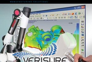
AME Exhibitor Spotlight – Verisurf
Verisurf Software provides complete software and hardware solutions for computer-aided inspection, tool building, and reverse engineering to manufacturers around the world. The Verisurf Inspection Suite tackles any inspection challenge head-on. It offers a unique, CAD-based architecture that can read all file formats, interoperate with any common mobile or stationary CMM (including arms, trackers, and scanner systems) and has the best reporting capabilities of any application on the market. The suite integrates beautiful, color images highlighting any deviation between measured parts and the nominal CAD model. And full Windows compliance assures that the Verisurf Inspection Suite is easy to learn and deploy. Verisurf’s Automated Inspection Suite sets a new standard for ease-of-use when authoring automated inspection programs for CMMs. Using the suite’s intuitive graphical interface, just point and click on the model features you want to include in your inspection plan. Operators have full control over every possible parameter of probe motion; can easily drag, drop, and group inspection steps and even preview CMM and probe kinematics before running the plan on a CMM. Already have a CMM? With Verisurf’s optional Universal CMM software, you can program and drive just about any brand of CMM without the expense of a controller or probe [...]
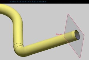
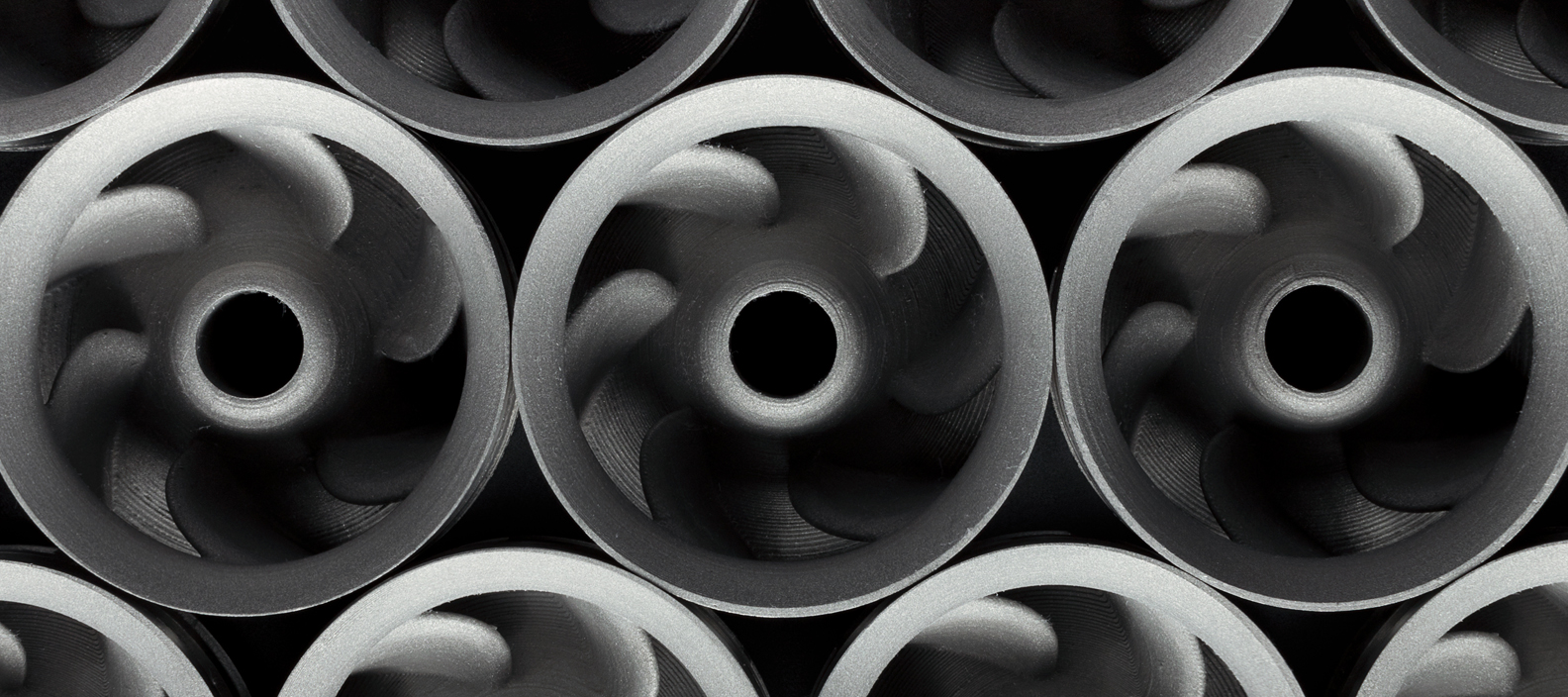
Reverse Engineering a 3D Pipe
This blog article will illustrate how to extract the centerline of a 3D pipe with compound angles. Extracting the centerline of a 3D pipe that contains angles in 2 dimensions is not that complicated. However, when you have compound angles, and the tube is bending in the X, Y, and Z directions simultaneously, extracting the centerline can be quite challenging. For example, below we have a prototype of ½ of a bicycle handle, printed on the HP Printer, in Nylon 12. It contains bends in compound angles. Let’s say you don’t have the CAD file to work with and would like to extract the centerline, so that you can create a true CAD file, improve it, and then eventually create a manufacturing drawing . . . One solution to accomplish this is to use Geomagic Design X software and this is how it would work. First, you would need to capture the physical geometry of the handle bar using a 3D scanner and then export an STL file. Next, import the STL file into Geomagic Design X. Design X has a function called: Sweep Wizard. With a few clicks, it produces a fully editable feature tree to create this shape. But what is [...]
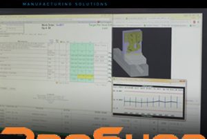
ProShop – AME 2017 Featured Exhibitor
A featured exhibitor at this year’s Advanced Manufacturing Expo, ProShop is a leader in Manufacturing ERP and shop management software. ProShop, a modern web based ERP that can manage every aspect of your front office and shop floor. Known for its interface and web-based navigation, ProShop links all corners of a company together to allow seamless management and decision making. It includes a collection of features for ERP, MES, and QMS modules is the only 3rd Party Solution Provider for Mastercam in the Shop Management Software and integrates cutting tool management with Mastercam. The founders are manufacturers at heart and they originally created ProShop to help manage their own CNC shop. At first, they only had the intention to use it privately for their own business. However, over the years they continued to develop and refine the software. It received favorable praise from customers and peers, who eventually urged them to release ProShop to the public market. It has grown today to be a trusted and highly efficient solution for machine shops, fabricators, job shops, contract manufacturers and others in highly regulated industries. Watch the video below to learn more. [one_full last="yes" spacing="yes" center_content="no" hide_on_mobile="no" background_color="" background_image="" background_repeat="no-repeat" background_position="left top" hover_type="none" link="" border_position="all" border_size="0px" [...]
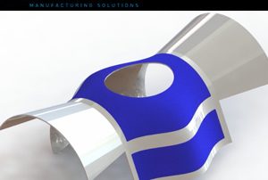
SolidWorks 2017 3D Offset on Curved Surfaces
There is new functionality in SolidWorks 2017 that allows you to offset 3D curves on a surface. Offsetting 2D geometry is very efficient. It allows you to quickly grab 2D geometry and create a same shape contour with a specified gap distance. However, when working with 3D sketches containing 3D curves, it’s not as simple. As of SolidWorks 2016, many steps were required to accomplish this task. Now in SolidWorks 2017, it got a whole lot easier. Notice in the example below, we have a surface body that contains 3D curved boundaries. To create the 3D offset, you can simply go to the sketch tab, and click on the Offset on Surface button. This quickly launches you into a 3D sketch environment. From this point, all you need to do is click directly on the edges, enter your offset value, and choose your offset direction. If you wanted to choose the boundary on all sides of the face, you can just choose the face itself, and the command will propagate the edges accordingly. This command is ideal to use if you wanted to punch out the center of a 3D surface, or even create the design for an over molding, all the meanwhile [...]