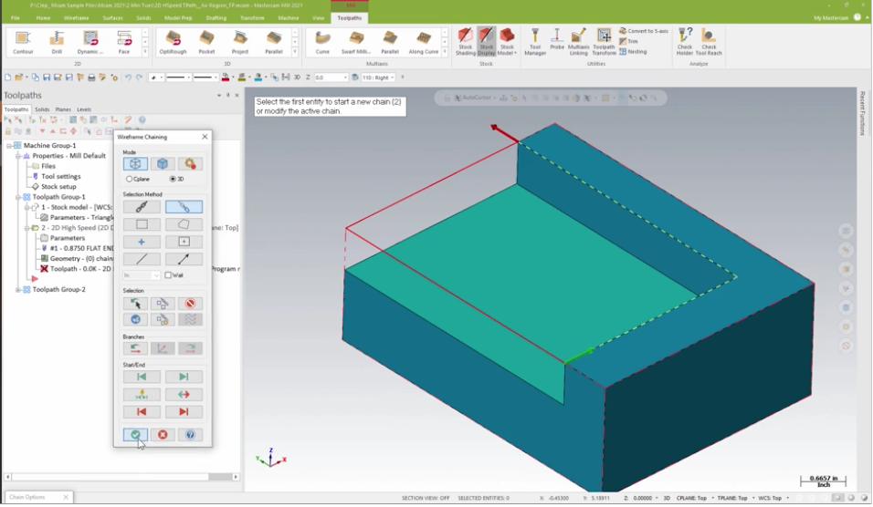
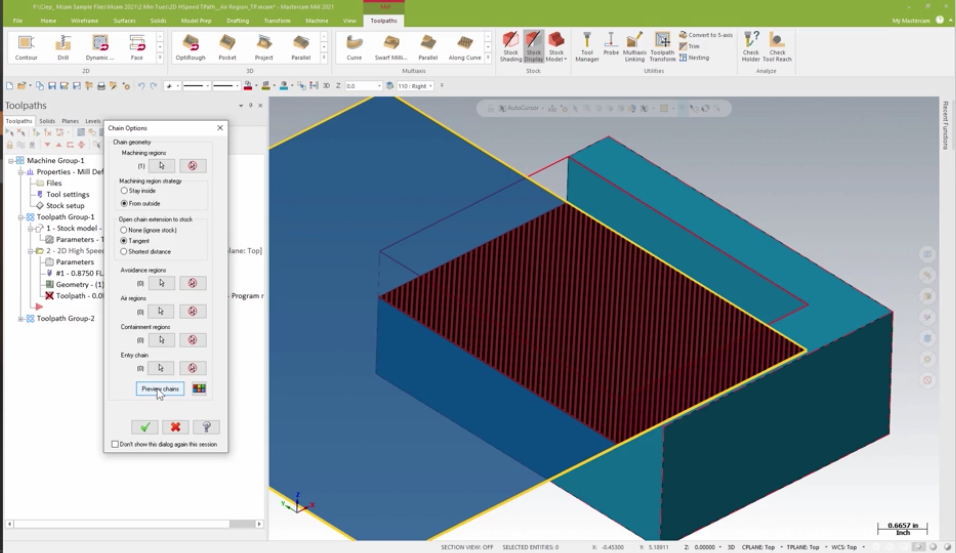
This article will cover using Mastercam Air Regions when cutting open geometry in the 2D Highspeed Dynamic toolpath. With multiple open sides many times programmers will try to select the inside edges of the open Geom. In this example, we will select the geometry along the two walls. This image below illustrates the preview chains utility that shows what the toolpath is calculating to be cut.
With the machining region set to cut from the outside and no open-chain extensions set you can see that the cut area in the hashed red and black has been closed by a diagonal line.
The blue area represents the air region for the toolpath, allowing the tool to move through this area with nothing to avoid. Stock has been defined for the part so switching the open-chain extension to stock will trim the cut area to open edges of the machining region.
Where we run into issues is if the stock has not been defined for the part. For example, mirrored geometry.
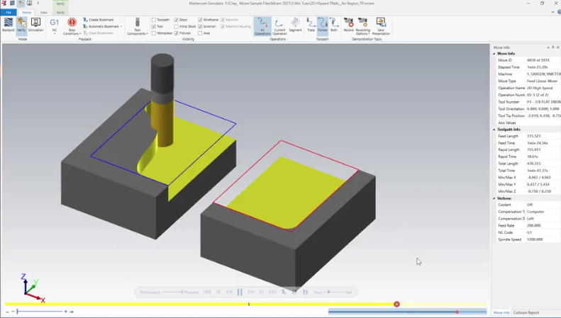
The stock has not been defined for the mirrored part when analyzing the toolpath the preview chains utility shows the cut area has shifted to the stock location for the first part and the air region beyond what is required.
How can we fix this?
By rechaining the geometry as a closed boundary and switching the machining region strategy to stay inside.
We now have a toolpath that is being controlled again by the boundary. To get the tool to overlap the open edge we need to incorporate air regions. Select the geometry on the open edges to be defined as the air region.
Now when the toolpath is reviewed you will see there is more control over the machining and air regions.
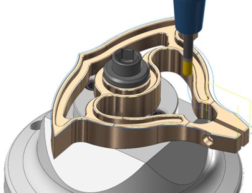
Using the air region method will work really well with odd-shaped regions as well.
Please be sure to sign up for our 2 Minute Tuesday video series to receive tips and tricks like this one in video form every week. More info at the button below.






Leave A Comment